Continue to Site

Welcome to EDAboard.com

Welcome to our site! EDAboard.com is an international Electronics Discussion Forum focused on EDA software, circuits, schematics, books, theory, papers, asic, pld, 8051, DSP, Network, RF, Analog Design, PCB, Service Manuals... and a whole lot more! To participate you need to register. Registration is free. Click here to register now.

[moved] Solving negative inductance solenoid in CST

Status
Not open for further replies.

bahramse

Newbie level 6
Newbie level 6
Joined
Aug 23, 2010
Messages
11
Helped
0
Reputation
0
Reaction score
0
Trophy points
1,281
Location
iran
Visit site
Activity points
1,357
Hello ,
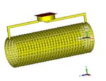
I designed a simple solenoid coil in CST and after the simulation it gives me negative value for inductance,
I have read some post about this issue and some propose to rotate the coil or something like this which I didnt understand at all.
the most interesting part is that the inductance is frequency dependent, I mean in some frequency range it is positive and in some region it goes to zero and then to negative.
Can anybody help me to fix this problem, thank you all in advance.
 

it gives me negative value for inductance

Negative inductance means capacitance. If you see this at low frequency, typically this results from a gap (not connected) somewhere in the model.

- - - Updated - - -

the most interesting part is that the inductance is frequency dependent, I mean in some frequency range it is positive and in some region it goes to zero and then to negative.

Search keyword: self resonance
 

thank you very much for your response ,
the gaps are between the turns of the coil, you might be right but when I calculate the capacitance of the coil, it gives me different number.
I am trying to say that, if the coil behaves as an capacitor, it should has positive inductance but very small number.
for instance when the inductance of the coil is positive the capacitance of coil is positive as well but very small.
I still didnt figure out why it is negative and how i can solve this...
 

Posting the observed impedance versus frequency graph would provide quite a little more clarity...
 

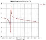
Sure , the attached files are the Z matrix, the model and the Inductance,
Thank you for your help in advance. Z matrix.JPG model.JPGinductance.JPG
 

thank you very much for your response ,
the gaps are between the turns of the coil, you might be right but when I calculate the capacitance of the coil, it gives me different number.
I am trying to say that, if the coil behaves as an capacitor, it should has positive inductance but very small number.

You misunderstood what I wrote.

In my long time in EM simulation support, I have seen many cases where the inductor showed "negative" inductance (=capacitive behaviour) because by mistake there was some gap in the conductor path. In these cases, series resistance was also large (infinite) instead of normal ohmic losses. You should check for that. I think you have a bad connection somewhere.
 

I am sorry about that, Actually I checked the model and I couldn't find anything, this is strange that in some special range of frequency this phenomena happens, the attached file is the ohmic resistance and as we see it just has peak in some special frequency not whole the frequency band, what is this special frequency? .rsistance.JPG, do you thinks again this could be because of miss connection or there is something special about this.
thank you
 

Resistance looks ok.

What equation do you use to calculate inductance?
Can you show S11 in Smith chart?
 

Actually I use CST post processing to calculate the Inductance , I use Post processing-->S-Parameter-->Coil Parameter-->Inductance. Is there any other way to calculate the Inductance?

S-parameter.JPG
based on this figure, it looks like resonance frequency but it is very weak. is this the self resonance frequency of coil?

s11 Impedance view.JPG
S11 impedance view
S11 in polar.JPG
S11 polar view.

thank you very much for all your help.
 

That's more or less open circuit with a "weak" series resonance around 540 MHz. Still looks like the "coil with gap" as assumed by volker muehlhaus. We now have six different plots basically showing the same problem.

If you actually want to make an inductor you should review your geometry.

- - - Updated - - -

P.S.: If it's not a gap (discontinuity), it's an unusually high resistance conductor. It's not easily to determine in small analysis bandwidth.
 

For lower frequency we have these results, It is really strange , the peak value is much larger !
S-parameter2.JPGinductance2.JPG


Ok, this is your inductance. It is an inductor at low frequency. The parasitic C between the turns makes it a L||C and the effective inductance increases with frequency. At 240MHz we have the parallel self resonance freqency. Above that, the parasitic capacitance between the turns dominates and the inductor behaves like a capacitor.

All this looks typical. Before, we just looked at the wrong frequency range, much above the self resonce frequency.
 
Thank you very much for your response Volker, Just the last question , if the self resonance frequency is at 240 MHZ why we dont have drop in S-Parameters at 240 MHz and it is at higher frequency ?

thank you again for all your help.
 

why we dont have drop in S-Parameters at 240 MHz and it is at higher frequency ?
You didn't yet look at low frequency S-parameters, isn't it? There's obviously a second resonance around 540 MHz, but much smaller.
 

Actually I attached the S-parameter in my previous post , we only have a 5 dB drop in 540 MHz and we dont have any drop close to 240 Mhz.
 

O.K., the S11 magnitude curve is a bit suprizing. An important information would be however S11 phase, |S11| = 1 doesn't tell if it's open or short circuit.

You get all essential information from the Smith diagram (polar S11 plot) as shown in post #9, for better resolution the display range should be restricted to the "passive" range |S11| <= 1.
 

Thank you very much for your response Volker, Just the last question , if the self resonance frequency is at 240 MHZ why we dont have drop in S-Parameters at 240 MHz and it is at higher frequency ?

At inductor self resonance we have |jwL| = |1/jwC| and this creates an open circuit from the inductance and the parallel capacitance between the turns. Open circuit, total reflection, no dip in S11 expected there!

The dip in S11 is seen where your coil radiates as an antenna, or there is another reason for loss that bring the resistance to 50 Ohm. This is not the self resonance from L|| C.
 
Status
Not open for further replies.

Similar threads

Part and Inventory Search

Welcome to EDABoard.com

Sponsor

Back
Top