Continue to Site

Welcome to EDAboard.com

Welcome to our site! EDAboard.com is an international Electronics Discussion Forum focused on EDA software, circuits, schematics, books, theory, papers, asic, pld, 8051, DSP, Network, RF, Analog Design, PCB, Service Manuals... and a whole lot more! To participate you need to register. Registration is free. Click here to register now.

[Moved.]Regarding 7segemnt multiplexing.

Status
Not open for further replies.

sruthi009

Newbie level 5
Joined
Mar 3, 2012
Messages
10
Helped
0
Reputation
0
Reaction score
0
Trophy points
1,281
Activity points
1,396
Hi,

I wants to get the output of seven segment(0 to 999) multiplexing,thats why i searched in google i got the program for seven segment multiplexing,but in that coding four seven segments are connected to microcontroller directly,but in my board, thery connected seven segment through buffer to miccorcontroller.Now which one i have to change coding part to get the out,i pasted the code below.


Code C - [expand]
1
2
3
4
5
6
7
8
9
10
11
12
13
14
15
16
17
18
19
20
21
22
23
24
25
26
27
28
29
30
31
32
33
34
35
36
37
38
39
40
41
42
43
44
45
46
47
48
49
50
51
52
53
54
55
56
57
58
59
60
61
62
63
64
65
66
67
68
69
70
71
72
73
74
75
76
77
78
79
80
81
82
83
84
85
86
87
88
#include<reg51.h>
 sbit dig_ctrl_4=P1^0; // Control pins for the seven segments
 sbit dig_ctrl_3=P1^1;
 sbit dig_ctrl_2=P1^2;
 sbit dig_ctrl_1=P1^3;
 unsigned char dig_disp=0;
 int min2;
 int min1;
 int sec2;
 int sec1;
 char digi_val[10]={0x40,0xF9,0x24,0x30,0x19,0x12,0x02,0xF8,0x00,0x10};
 
void delay()        // Function to provide time delay using Timer 1.
    {
    int i;
    for(i=0;i<20;i++)
    {
        TL1=0xFD;
         TH1=0x4B;
         TR1=1;
         while(TF1==0);
         TR1=0;
         TF1=0;
    }
}
   
 
void display() interrupt 1        // Function to display the four digit number using multiplexing on seven segment. It uses Timer 0 interrupt to display the four digits one by one after a time delay of 2.5 milli second
{
    TL0=0x36;
    TH0=0xf6;
    P2=0xFF;
    dig_ctrl_1 = dig_ctrl_3 = dig_ctrl_2 = dig_ctrl_4 = 0;
    dig_disp++;
    dig_disp=dig_disp%4;
    switch(dig_disp)
    {
        case 0:
        P2=digi_val[sec1];
        dig_ctrl_1 = 1;
        break;
 
        case 1:
        P2=    digi_val[sec2];
        dig_ctrl_2 = 1;
        break;
   
        case 2:
        P2=    digi_val[min1];
        dig_ctrl_3 = 1;
        break;
   
        case 3:
        P2=    digi_val[min2];
        dig_ctrl_4 = 1;
        break;
    }
}


void main()
{
 
    TMOD=0x11;        // Intialize Timer 0
    TL0=0x 36;
    TH0=0xF6;
    IE=0x82;
    TR0=1;        //Start timer0
    while(1)        // Forward counting
     {
          min2=min1=sec2=sec1=0;
          for(min2=0;min2<10;min2++)
          {
               for(min1=0;min1<10;min1++)
               {
                for(sec2=0;sec2<10;sec2++)
                {
                     for(sec1=0;sec1<10;sec1++)
                     {
                    delay();
                    }
                }
               }
        }
     }
}

 
Last edited by a moderator:

For Idea see -> Seven Segment Display Multiplexing Example Code using C For Newbies https://www.edaboard.com/blog/1357/
for code, circuit, etc

---------- Post added at 17:02 ---------- Previous post was at 17:01 ----------

attachment.php


---------- Post added at 17:05 ---------- Previous post was at 17:02 ----------

Hi,

but in my board, thery connected seven segment through buffer to miccorcontroller.Now which one i have to change coding part to get the out,i pasted the code below.

Publish the circuit
 
Last edited:

Hi,

Thanks, for ur reply,but my board having four seven segment digits,these four are connected through decoder ic (74ls47) to 89v51rd2.but i got circuit diagram for seven segment directly connected to the 89c51.How can i display 0 to 999 on seven segments.please tel me the step by step procedure.Thanks in advance.
 

There 2 methods of interfacing LED with the Microcontroller Intel 8051/8951.

1.Using lookup table. This uses 7 output pins of microcontroller
2.Using 7447 decoder. This method uses 4 output pins of microcontroller
The difference between the two main methods is simple and clear. In both the cases, microcontroller communicates with external world through its ports. But, in the 1st case, we connect all the 8 pins of the port directly to the LED and control the voltage through the ports manually to display the desired number. But, in the second case, we send the BCD of the number that we wanted to display to a middleware IC 7447, the BCD to LED code converter, which by itself gives out the correspondent 7 segment codes to the LED.


74LS47 has open collector outputs ,you have to connect each output to a resistance say 220Ω and then to the 7 segment digits which should be a common anode one.

You need to add pull up resistors to the output.Or use a common anode display without the pull up resitors.
Common anode of your seven segment display must be connected to the +5V power supply. Each cathode of the seven segment display must be connected in serial with a resistance of arround 270 ohms to the dedicated open collector output of the 74ls47.

Note that you can't easily use a common-cathode display. If you use a pull-up resistor, the output will be forced high (+V, through the resistor) when the segment output is inactive, and pulled low when active. With a common-cathode display connected, this is the opposite of how the device expects to decode the data to 7-segment - the segments will be inverted - segments will light when they should be off and be off when they should light.

---------- Post added at 12:10 ---------- Previous post was at 12:06 ----------

**broken link removed**
 
Last edited:

FOR MULTIPLEXING:-
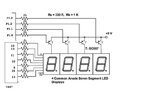
Here in this case, the IC7447 takes the Binary Coded Decimal (BCD) as the input and outputs the relevant 7 segment code. The 7447 converts the four input bits (BCD) to their corresponding 7-segment codes.
multi.JPG
 

PIN 7,1,2,6 of IC7447 will go to P2.0 to P2.3
The number required to display is sent as the lower nibble of the Port 2 of the Microcontroller. The 7447 converts the four input bits (BCD) to their corresponding 7-segment codes. The outputs of the 7447 are connected to the 7-segment display.
mul1.GIF
 
Last edited:

Thanks u sir,now problelm with coding part,control pins of 7 segment are P0.7 to P0.4,and decoder inputs are P0.0 to P0.3,im posting coding part below plz check once that one,i have to pass value to dat perticular four pins? i got the wrong output, how to display 0 to 9999.
// Program to demonstrate the principle of seven segment multiplexing. The program uses a counter which counts from 0 to 9999


Code C - [expand]
1
2
3
4
5
6
7
8
9
10
11
12
13
14
15
16
17
18
19
20
21
22
23
24
25
26
27
28
29
30
31
32
33
34
35
36
37
38
39
40
41
42
43
44
45
46
47
48
49
50
51
52
53
54
55
56
57
58
59
60
61
62
63
64
65
66
67
68
69
70
71
72
73
74
75
76
77
78
79
80
81
82
83
84
85
86
87
88
89
#include<reg51.h>
 sbit dig_ctrl_4=P0^7; // Control pins for the seven segments
 sbit dig_ctrl_3=P0^6;
 sbit dig_ctrl_2=P0^5;
 sbit dig_ctrl_1=P0^4;
 unsigned char dig_disp=0;
 int min2;
 int min1;
 int sec2;
 int sec1;
 char digi_val[10]={0x40,0xF9,0x24,0x30,0x19,0x12,0x02,0xF8,0x00,0x10};
 
void delay()        // Function to provide time delay using Timer 1.
    {
    int i;
    for(i=0;i<20;i++)
    {
        TL1=0xFD;
         TH1=0x4B;
         TR1=1;
         while(TF1==0);
         TR1=0;
         TF1=0;
    }
}
   
 
void display() interrupt 1        // Function to display the four digit number using multiplexing on seven segment. It uses Timer 0 interrupt to display the four digits one by one after a time delay of 2.5 milli second
{
    TL0=0x36;
    TH0=0xf6;
    P0=0xFF;
    dig_ctrl_1 = dig_ctrl_3 = dig_ctrl_2 = dig_ctrl_4 = 0;
    dig_disp++;
    dig_disp=dig_disp%4;
    switch(dig_disp)
    {
        case 0:
        P0=digi_val[sec1];
        dig_ctrl_1 = 1;
        break;
 
        case 1:
        P0= digi_val[sec2];
        dig_ctrl_2 = 1;
        break;
   
        case 2:
        P0= digi_val[min1];
        dig_ctrl_3 = 1;
        break;
   
        case 3:
        P2= digi_val[min2];
        dig_ctrl_4 = 1;
        break;
    }
}


void main()
{
 
    TMOD=0x11;        // Intialize Timer 0
    TL0=0x36;
    TH0=0xF6;
    IE=0x82;
    TR0=1;        //Start timer0
 
    while(1)        // Forward counting
     {
          min2=min1=sec2=sec1=0;
          for(min2=0;min2<10;min2++)
          {
               for(min1=0;min1<10;min1++)
               {
                for(sec2=0;sec2<10;sec2++)
                {
                     for(sec1=0;sec1<10;sec1++)
                     {
                    delay();
                    }
                }
               }
        }
     }
}

 
Last edited by a moderator:

The folowing prowing will give you idea. The program is not tested on h/w. Try it and let me know.
It displays a 4 digit number using multiplexing method.
See post #5 and #6 for connection.

Code C - [expand]
1
2
3
4
5
6
7
8
9
10
11
12
13
14
15
16
17
18
19
20
21
22
23
24
25
26
27
28
29
30
31
32
33
34
35
36
37
38
39
40
41
42
43
44
45
46
47
48
49
50
51
52
53
54
55
56
57
58
59
60
61
62
63
64
65
66
67
#include<8051.h>
__sbit __at(0x90) dig_ctrl_4;   //=P1^0; // Control pins for the seven segments
__sbit __at(0x91) dig_ctrl_3;   //=P1^1;
__sbit __at(0x92) dig_ctrl_2;   //=P1^2;
__sbit __at(0x93) dig_ctrl_1;   //=P1^0;
unsigned char  DecimalToBCD (unsigned char decimalByte);
void fnd_display(unsigned char val,int pos);
 
unsigned int n=0;
int digits[4];
 
 
void main()
{
int i,j;
unsigned char digit;
i=0;
P1=0;
P2=0;
dig_ctrl_1=1;
dig_ctrl_2=1;
dig_ctrl_3=1;
dig_ctrl_4=1;
n=1234;
while(n){
digits[i]=n%10;
i++;
n=n/10;
 
}
 
while(1){
for(i=0;i<=3;i++){
Delayms(5); //put delay of 5 mS. Adjust for clear visibility. Write your own routine
digit=digits[i];
fnd_display(DecimalToBCD(digit),i); //try to send digit without conversion and see what happens
}
}
}
//////////////////////////////////
void fnd_display(unsigned char val,int pos){
 
switch(pos){
 
case 0:
dig_ctrl_1=0;
break;
case 1:
dig_ctrl_2=0;
break;
case 2:
dig_ctrl_3=0;
break;
case 3:
dig_ctrl_4=0;
break;
}
P2=val;
return ;
} 
//////////////////////////////////
unsigned char  DecimalToBCD (unsigned char decimalByte)
{
  return (((decimalByte / 10) << 4) | (decimalByte % 10));
} 
 
/////////////////

 
Last edited:

Thanks u sir,but the following code is not working,while pressing reset button just zero showing on four seven segment digits,after that its disappeared.and i added just delay function.


Code C - [expand]
1
2
3
4
5
6
7
8
9
10
11
12
13
14
15
16
17
18
19
20
21
22
23
24
25
26
27
28
29
30
31
32
33
34
35
36
37
38
39
40
41
42
43
44
45
46
47
48
49
50
51
52
53
54
55
56
57
58
59
60
61
62
63
64
65
66
67
68
69
#include<reg51.h>
sbit dig_ctrl_4=P0^7; // Control pins for the seven segments
sbit dig_ctrl_3=P0^6;
sbit dig_ctrl_2=P0^5;
sbit dig_ctrl_1=P0^4;
unsigned char  DecimalToBCD (unsigned char decimalByte);
void fnd_display(unsigned char val,int pos);
 
unsigned int n=0;
int digits[4];
 
void Delayms(int j)
{
int i;
for(i=0;i<=j;i++);
}
void main()
{
int i;
unsigned char digit;
i=0;
P0=0;
 
dig_ctrl_1=1; 
dig_ctrl_2=1;
dig_ctrl_3=1;
dig_ctrl_4=1;
n=1234;
while(n){
digits[i]=n%10;
i++;
n=n/10;
 
}
 
while(1){
for(i=0;i<=3;i++){
Delayms(5000); //put delay of 5 mS. Adjust for clear visibility. Write your own routine
digit=digits[i];
fnd_display(DecimalToBCD(digit),i); //try to send digit without conversion and see what happens
}
}
}
//////////////////////////////////
void fnd_display(unsigned char val,int pos){
 
switch(pos){
 
case 0:
dig_ctrl_1=0;
break;
case 1:
dig_ctrl_2=0;
break;
case 2:
dig_ctrl_3=0;
break;
case 3:
dig_ctrl_4=0;
break;
}
P0=val;
return ;
} 
//////////////////////////////////
unsigned char  DecimalToBCD (unsigned char decimalByte)
{
  return (((decimalByte / 10) << 4) | (decimalByte % 10));
}


/////////////////

In my code I used 4 pins of P1 port to control the FND selection lines and used 4 pins of P2 port to accept the lower nibbles of a variable.

But you have modified my code. But according to your code you are using 4 pins of P0 port to control the FND selection lines and using the same port to send data to IC7447!! That means bit 7 to bit 4 of port P0 (which control the transistors)receiving 0000 at one go.
 

S, i modified ur code ,y bcoz i didnt get anything when i download ur code.
 
Last edited:

In that case the statement

P0=val;
will not work.

You have to transfer lower 4 bits one by one to each of the 4 pins(connected to 7447) of P0.
Ok I willl give you such code.
 

As you told "You have to transfer lower 4 bits one by one to each of the 4 pins(connected to 7447) of P0".u mean no need to mention control pins in coding part? please give me coding part.
 

in my board they used single port Po for control pins (4) of 7 segment and decoder four inputs ,with out chaging the connectiion i have to write the coding part.According to my connection plz tel me da coding.

According to your h/w connection if you send 1 byte of data to port P0, out of the 8bits higher 4 bits (7 to 4) will control the lines connected to transistors and remaining 4 bits(3 to 0) will send a BCD number to the 7447.

For example:

11101001 is a 8bit binary number.
Here higher 4 bits 1110. Lower 4 bits(nibble) 1001

if you write p0=b'11101001'
That means 1110 will control your FND selection lines. It will turn on the transistor connected to the FND representing 1's place. And 1001 will be passed to IC7447 as BCD number. So 9 will be displayed at the FND representing 1's place.
 

Sir, i need coding part according to my hardware connection.
 
Last edited:

I think there is some thing which is escaping our eyes.

Aso needs some details like:-
P0.0-->A
P0.1-->B
P0.2-->C
p0.3-->D
OR
P0.0-->D
P0.1-->C
P0.2-->B
p0.3-->A

This makes large difference
Publsh the circuit diagram and a picture of the board
 

Gud evening sir, i have written program for stopwatch,for dis i used four seven segments and 3 pushbuttons.My program is working except one pushbuuton,PB1 for counting and PB2 for reset and PB3 for stopping,but in my program PB3 is not working ,where is prob,plz tel me sir.

Thanks in Advance.

//Program to make a stopwatch


Code C - [expand]
1
2
3
4
5
6
7
8
9
10
11
12
13
14
15
16
17
18
19
20
21
22
23
24
25
26
27
28
29
30
31
32
33
34
35
36
37
38
39
40
41
42
43
44
45
46
47
48
49
50
51
52
53
54
55
56
57
58
59
60
61
62
63
64
65
66
67
68
69
70
71
72
73
74
75
76
77
78
79
80
81
82
83
84
85
86
87
88
89
90
91
92
93
94
95
96
97
98
99
100
101
102
103
104
105
106
107
108
109
110
111
112
113
114
115
116
117
118
119
120
#include<reg51.h>
#define p0 P0
#define p3 P3
 
unsigned int sec1,sec2;
int sec1_1,sec1_2,sec2_1,sec2_2;
 
unsigned int digi_val[10]={0x00,0x01,0x02,0x03,0x04,0x05,0x06,0x07,0x08,0x09};
sbit dig_ctrl_1=P0^7;  // Declare the control pins of seven segments
sbit dig_ctrl_2=P0^6;
sbit dig_ctrl_3=P0^5;
sbit dig_ctrl_4=P0^4;
 
sbit start_pin = P3^2;  // Start pin to start the watch.
sbit stop_pin = P3^3;  // Stop pin to stop the watch.
sbit reset_pin = P3^4;  // Reset pin to reset the watch.
int s,t;
 
void mplex_delay(unsigned int j)  // Function to provide a time delay of approximatelty one second using Timer 1
{
int i;
for (i=0;i<=j;i++);
  //for(j=0;j<=500;j++);
}
 
void digi_out(unsigned int current_num)
{
    p0=digi_val[current_num];
    
     mplex_delay(0);
}
 
void display(unsigned int dig1,unsigned int dig2)  // Function to display the digits on seven segmnet. For more details refer seven segment multiplexing.
{
sec1_2=dig1%10;
sec1_1=dig1/10;
sec2_2=dig2%10;
sec2_1=dig2/10;
TMOD=0x01;  //Enable Timer 0
TL0=0xFF;
TH0=0xDB;
TR0=1;  // Triger Timer 0
while(TF0==0)
{
  dig_ctrl_1 = 1;
  dig_ctrl_2 = dig_ctrl_3 = dig_ctrl_4 = 0;
  digi_out(sec1_1);
  dig_ctrl_2 = 1;
  dig_ctrl_1 = dig_ctrl_3 = dig_ctrl_4 = 0;
  digi_out(sec1_2);
  dig_ctrl_3 = 1;
  dig_ctrl_2 = dig_ctrl_1 = dig_ctrl_4 = 0;
  digi_out(sec2_1);
  dig_ctrl_4 = 1;
  dig_ctrl_2 = dig_ctrl_3 = dig_ctrl_1 = 0;
  digi_out(sec2_2);
}
 
TR0=0;
TF0=0;
}
 
 
void main()
{
while(1)
{
start:  // Segment to start the stop watch
  
  dig_ctrl_1 = 0;
  
  
  dig_ctrl_2 = 0;
  dig_ctrl_3 = 0;
  dig_ctrl_4 = 0;
  P0 = 0xFF;
  s = t = 0;
  while(start_pin ==  0)// Check if start pin is pressed
  {
  display(0,0);
  }
 
 
stopwatch:  // Segment to stop the watch
for (sec1=s;sec1<=99;sec1++)
{
   if (stop_pin == 1&& start_pin==0 )  //Check if stop pin is pressed
   break;
  for (sec2=t;sec2<=99; sec2++)
  {
    if (stop_pin == 1 && start_pin==0)  //Check if stop pin is pressed
    break;
    
    display(sec1,sec2);
    }
}   
  
 
    s = sec1;
    t = sec2;
 
  while ( stop_pin == 1 && start_pin == 1 )  //Check if start pin or reset pins are not pressed
 {
 display(sec1,sec2);
 }
 if (start_pin == 1 )  //Check if start pin is pressed
 {
 goto stopwatch;
 }
 else
 {
 if (stop_pin == 1 )  //Check if reset pin is pressed
 {
 s = t = 0;
 goto start;
 }
 }
  
}
}


z
 
Last edited by a moderator:

What type of switches are you using? If they are sub miniature push to on type switches then as soon as you release a switch, logic will change.
Next , Try to avoid "goto" statement. It creates Spaghetti code. Search wiki with the term, you will know.
 
Last edited:

In my program one pushbutton for counting(0-9) ,another for stop,and another for where we stopped from there to it has to count,but in my program thrid b uuton is not working,where is the mistake plz tel me sir.


Code C - [expand]
1
2
3
4
5
6
7
8
9
10
11
12
13
14
15
16
17
18
19
20
21
22
23
24
25
26
27
28
29
30
31
32
33
34
35
36
37
38
39
40
41
42
43
44
45
46
47
48
49
50
51
52
53
54
55
#include<reg51.h>
#define p0 P0
#define p3 P3   
sbit p1=P3^2;
sbit p2=P3^3;
sbit p3=P3^4;


void wait(int j)
{
long int i;
 
for(i=0;i<j;i++);
}
 
void reset()
{
 
for(p0=0x00;p0<=0xf9;p0++)
{
wait(10000);
}
}


void main()
{
 
 
    if(p2==1)
    {   
        
        p0=0xff;
        for(p0=0xf0;p0<0xf9;p0++)
        {
            wait(10000);
            if(p1==1)
            break;
            if(p3==1)
            
            reset();


        }   
 
        
    }
 
}

 
Last edited by a moderator:

In my program one pushbutton for counting(0-9) ,another for stop,and another for where we stopped from there to it has to count,but in my program thrid b uuton is not working,where is the mistake plz tel me sir.


Code C - [expand]
1
2
3
4
5
6
7
8
9
10
11
12
13
14
15
16
17
18
19
20
21
22
23
24
25
26
27
28
29
30
31
32
33
34
35
36
37
38
39
40
41
42
43
44
45
46
47
48
49
50
51
52
53
54
55
#include<reg51.h>
#define p0 P0
#define p3 P3   
sbit p1=P3^2;
sbit p2=P3^3;
sbit p3=P3^4;


void wait(int j)
{
long int i;
 
for(i=0;i<j;i++);
}
 
void reset()
{
 
for(p0=0x00;p0<=0xf9;p0++)
{
wait(10000);
}
}


void main()
{
 
 
    if(p2==1)
    {   
        
        p0=0xff;
        for(p0=0xf0;p0<0xf9;p0++)
        {
            wait(10000);
            if(p1==1)
            break;
            if(p3==1)
            
            reset();


        }   
 
        
    }
 
}


Assuming that you are using 89S51, remember all the ports, upon RESET are configured as inputs, ready to be used as input ports. When the first 0 is written to a port, it becomes an output. To reconfigure it as an input, a 1 must be sent to the port.
So after main, P0=0; will make it output (but not used in your programme)
and P3=0x1C; //00011100
Will make pin 2,3,4 of port P3 as input. Remember bit 3 is pin 2

Now for switch connection:-
input_switch.gif


For the left most connection, when the switch is closed, the associated pin go low. That is, (p0==0) will return true.

---------- Post added at 14:36 ---------- Previous post was at 14:34 ----------

Also save the value in a variable and upon resume, start counting from there
 

Status
Not open for further replies.

Similar threads

Part and Inventory Search

Welcome to EDABoard.com

Sponsor

Back
Top