ChineseSeller
Newbie level 3
Hi,
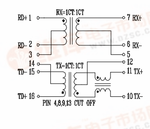
I'm trying to reuse some old unused LAN cards to connect to some microcontroller evaluation boards with ethernet support. I chopped off the PHY while keeping the rest. I am treating the RJ-45 to PHY circuitry as blackbox, while dealing with the wires coming out the transformer connecting the PHY. Connecting TX+ , TX- , RX+ , RX- pins to MCU through 1,2,3,6 pins of RJ-45 holes seems fairly easy, but I can't get hold of the idea of TXCT, RXCT pins (4,5 pins of RJ-45 holes). What are these pins for? How to treat them in general? The RC values connected with TXCT and RXCT are wildly different in different schematics. How sensitive are they for error free connection?
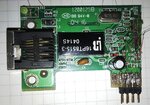
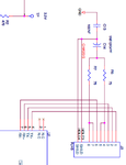
While looking for reference schematic, I found that different circuits connects them very differently, so I am very confused. I couldn't find any reference material explaining these pins clearly. Please have a look at the following pics of LAN card, transformer and schematic I am trying to cope with-


