Continue to Site

Welcome to EDAboard.com

Welcome to our site! EDAboard.com is an international Electronics Discussion Forum focused on EDA software, circuits, schematics, books, theory, papers, asic, pld, 8051, DSP, Network, RF, Analog Design, PCB, Service Manuals... and a whole lot more! To participate you need to register. Registration is free. Click here to register now.

[MOVED]my doubt on regarding the cypress related application PSOC..........

Status
Not open for further replies.

sridivya pathapati

Junior Member level 2
Joined
Feb 1, 2012
Messages
22
Helped
0
Reputation
0
Reaction score
0
Trophy points
1,281
Activity points
1,424
hiii...can u tell me that what are the API to be used to provide the system clock source and digital data as inputs for the two pwm's???
 

You would normally select the system clock in the project GLOBAL RESOURCES window of PSoC Designer. If you want to dynamically change the clocks then you would need to do that by manipulating the appropriate registers such as OSC_GO_EN, OSC_CR0 etc. See chapter 25 of the PSoC Technical Reference Manual page 443 onwards.

Similarly, you would configure the PWMs using the the PARAMETERS window of the PSoC Designer software when you have placed your PWM block. The API only covers things such as setting the pulse width and period. If you want to dynamically enable/disable the inputs/outputs then you will need to do it by manipulating the registers.

If any of the windows aren't visible, go to the VIEW menu and enable them.

Keith
 

i have to provide the digital data as inputs for the two PWM'S?? how can it be possible in psoc???
 

clarification of the doubt in designer software of PSOC..

hii...im using two PWM'S and their output is provided to a xor gate and in turn the xor gate output is given as input to another PWM16. My que is that how can the XOR GATE output can be given as input to PWM16??
 

Your objective isn't clear. "... im using two PWM'S and their output is provided to a xor gate ..." two PWMs have two outputs, not one.

A PWM has a clock and two values to set it up - one which defines the period and the other defines the mark-space ratio. The input is a clock. The output is a fixed frequency pulse train of variable mark-space ratio. The period and mark space ratio values would normally come from the software.

So, what is the clock to the first PWM and what defines the persiod & mark space ratio of it?

In what way is that intended to influence the second PWM?

What is the intended clock for the second PWM and where do the period and mark-space ratio values come from?

Keith.
 

i hav taken two PWM 8 Which have the inputs as system clock and the digital data as well...the outputs are provided to XOR GATE and finally the xor gate output is provided as input to PWM16..So my questions are

1) i will provide the common system clock to pwm8's and how can i give the digital data via the CPU?? As shall i have to use any coding part inorder to enable the digital data??

2) how the xor gate output can be provided as input to the PWM16 using the interconnect logic???
 

When you say the output of the XOR is the input to the PWM16, do you mean as the clock to the PWM16?

I assume the XOR gate is external to the PSoC?

Which chip are you using?

Which version of PSoC Designer are you using?

To connect the clock of the PWM16 to an external pin you select the clock in the GUI and select one of the row inputs as the clock source such as Row_0_Input_0. Then connect that to one of the columns such as GIE0. Then connect that column to an I/O pin. It should look something like this when you have done it:


Keith.
 

im using the chip CY29466-PXI chip and the version is 4.3 and it is PSOC1 . im using the XOR GATE output as clock and giving the enable signal also for the PWM16 as inputs..so how can the PWM16 work??kindly help in the interconnections??
 

Your software is out of date, but that shouldn't significantly affect things.

I am not clear what you are trying to achieve. Maybe you could draw a diagram of the connections you want and what you expect to get out of it. As I mentioned earlier, the output of a PWM is a fixed frequency. If you combine two PWMs and use that as the clock for another PWM, you still simply have a fixed clock and haven't really achieved anything.

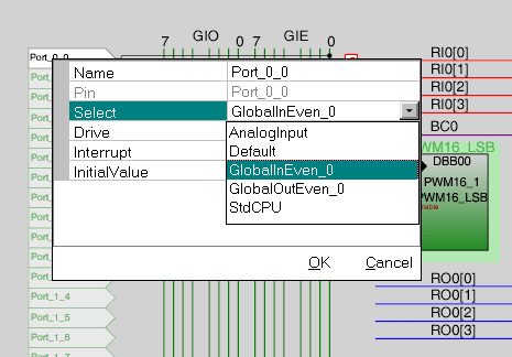
In terms of connections, you need to either read the manuals or simply click on objects in the GUI and see what options appear. To be quite honest, that is probably easier than reading the manuals! Most of the "wires" in the chip diagram are clickable. So, if you click on the RI0[0] line then click on the multiplexer symbol that pops up, you get the option to select where RI0[0} connects to:


If you then click on the first port Port_0_0 then another pop-up appears. On there you should change the "Select" to be the GlobalInEven_0 so it connects through to the correct line.

71_1328204122.gif


It may be worthwhile looking at some tutorials first Cypress Semiconductor

Keith.
 

Status
Not open for further replies.

Similar threads

Part and Inventory Search

Welcome to EDABoard.com

Sponsor

Back
Top