Continue to Site

Welcome to EDAboard.com

Welcome to our site! EDAboard.com is an international Electronics Discussion Forum focused on EDA software, circuits, schematics, books, theory, papers, asic, pld, 8051, DSP, Network, RF, Analog Design, PCB, Service Manuals... and a whole lot more! To participate you need to register. Registration is free. Click here to register now.

[Moved] LM317 High Current Power Supply

Status
Not open for further replies.

Suhas Anand

Junior Member level 2
Joined
Nov 1, 2014
Messages
24
Helped
5
Reputation
10
Reaction score
4
Trophy points
3
Activity points
151
Hello. I wanted to build a good psu with high current output for my projects and came across the circuit with a pnp pass transistor. Due to its simplicity i chose this circuit.
However I'm not able to get proper output after rigging up the circuit. When the pot is in the max position the output voltage is max. When i decrease slowly output voltage decreases and at a certain point the voltage starts increasing and shoots up to the max value again. When this happens the R3 gets really hot and I have burnt few resistors while testing. I dont know what s wrong with the circuit. Have been trying to debug for days.


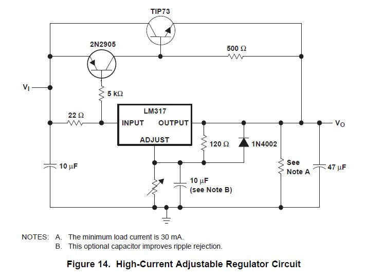
This is very simple 1.2 - 36V adjustable bench power supply with 5A of output current. Max input voltage is 37V and output is adjustable via potentiometer between 1.2 up to 36 volts. TIP147 PNP darlington transistor boosts the current of LM317 from 100mA to 5A. LM317 is the most useful and inexpensive adjustable regulator and for this circuit you can also use LM317L that can give 100mA, that's enough for transistor bias. D1 and D2 are protection diodes because when you turn the circuit off the output capacitors are discharging and can damage the transistor or regulator.

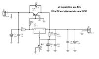
R1 is 2W and other resistors are 0.25W

R1 is LM317 current limiting resistor and R2 is Q1 bias resistor all capacitors are 50V RV1 is 5k multiturn volume pot.

100nf capacitors are in parallel with electrolytic capacitors to remove high frequency noise because large value electrolytic have large ESR and ESL and can't remove high frequency noise.

I will design a pcb for this circuit and add to this project.

Q1 needs heatsink and small fan. Maximum output power of adjustable power supply is 125W.
 
Last edited by a moderator:

Hello,

Your circuit looks wrong. You should connect LM317 out pin to transistor gate. LM317 just open the transistor and control the emitter or collector voltage(PNP or NPN).

Now where is your mistake..
Your transistor is always open and it is working on always maximum.

Why R3 getting hot ?
Just look at your circuit and tell me where transistor current will be go to ground ? There is a diode and caps. They are not passing current...

My soluiton :
Use NPN transistor and connect LM317 out pin to transistor gate.
Untitled.png
 

You are supplying high voltage than LN317 can handle. Its maximum limit is 36V across. That means Voltage difference between input and output. When output is lowered, this difference increases. Otherwise circuit is OK. Further lower R1 and R2 to 100-Ohm to increase current.
 

You are supplying high voltage than LN317 can handle. Its maximum limit is 36V across. That means Voltage difference between input and output. When output is lowered, this difference increases. Otherwise circuit is OK. Further lower R1 and R2 to 100-Ohm to increase current.

Dont you think the current is wrong ?

Current passing R3. Load and R3+Rpot looks parallel.
 

When value of Rpot is high, only then output voltage increases. It has two transistors to further increase output current. First transistor is connected in same style.
 

You are wrong i think.

His Base and Emitter voltages are constant. He cant adjust.
 

It is controlled by current not voltage. Base-emitter voltage is 0.6V.Current varies with load.
Your circuit will also work. It emitter follower configuration. It will drop more voltage. But in other circuit, internal current limiter circuit can also be used.
Perhaps you should consider a switching regulator. You can make a cheap one from an LM317 and a few common components.


https://www.fairchildsemi.com/datasheets/LM/LM7812.pdf
2038030300_1414881084.jpg

Pictured above is a circuit from the Fairchild LM7812 datasheet. This uses a power transistor and a power resistor to take on some of the workload enabling higher currents to be regulated
 

I have tried using 2n3055 npn transistors and it works(i.e. only when i have connected a load). I also read that such a circuit is very inefficient and had read many posts which suggested to use a pnp darlington. Hence I am stuck up with this circuit.
 

The circuit suggested by ALTERLINKS in post #5 can perfectly work with 2N3055. I don't see a disadvantage compared to a PNP darlington, except for having two power transistor packages instead of one. It's drop-out voltage is even lower by about 0.7 V.

In so far I don't understand in which regard you are stuck.
 

Hmmm.. I have few 2n3055 transistor lying around too. But I have already made pcb for the circuit using darlington. And its not working as R3 gets really hot when i try to decrease the pot.
 

Which circuit are you referring to? What is R3?

The circuit shown in post #1 can't work with NPN transistors.
 

Which circuit are you referring to? What is R3?

The circuit shown in post #1 can't work with NPN transistors.

I'm referring to the circuit shown in post #1. I have already fabricated the PCB just as shown in post #1. And its not working. Can you please tell me if there s anything wrong in that circuit? Coz i think i have not made any mistakes while rigging up the circuit.
 

Maybe your LM317 is faulty. Disconnect Collector of TIP147 and check output and working of LM317 circuit.
 

Nope lm317 is fine.. I have Checked it. The circuit works fine without the darlington.
 

Actually TIP147 is a Darlington. It is more sensitive. There is resistor R1, whose value is 1K and It is the cause of the problem. Change to 33-Ohm or 47-Ohm.
A small current through it is causing transistor to conduct. Reducing its value will lower the voltage drop on it and circuit behaviour will become normal.
 

By lowering the resistance more current will go to the darlington. That will contradict ur statement that darlington is more sensitive.
 

ALERTLINKS is right of course. LM317 has a minimal load current of 3 to 5 mA which always flows through R1. So any value above 200 ohm can cause the darlington to "open" partly.
 

Status
Not open for further replies.

Similar threads

Part and Inventory Search

Welcome to EDABoard.com

Sponsor

Back
Top