Thota Suresh Avionics
Member level 2

- Joined
- Jul 15, 2013
- Messages
- 45
- Helped
- 2
- Reputation
- 4
- Reaction score
- 2
- Trophy points
- 8
- Activity points
- 345
Hi
i am using pic30f5011 (16 bit) controller and mplabc30 compiler,to observe the output of the program i am using terminal programming....
My task is to read Voltage readings by using , i am new to SPI and ADS1118 ...
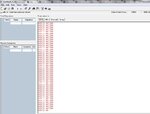
while running my code no errors... its showing fixed output as 65536..
am i missing something in SPI or ADS1118? plz help me anyone
showing output like this :
- - - Updated - - -
ADS1118 vs Microcontroller connection is like this
SCLK--------->SCLK
CS ----------->CS
SDO---------->SDI
SDI----------->SDO
4 Pullup resistors connected to SDO,SDI,SCLK,CS
And Variable pot is connected to ADS1118 analog channel AIN0 (ADS1118 -4th pin) to vary the in put voltage to ADS1118
i am using pic30f5011 (16 bit) controller and mplabc30 compiler,to observe the output of the program i am using terminal programming....
My task is to read Voltage readings by using , i am new to SPI and ADS1118 ...
while running my code no errors... its showing fixed output as 65536..
Code:
#define SCLK LATGbits.LATG6 //clock line
#define SDI LATGbits.LATG7 //SPI data input
#define SDO LATGbits.LATG8 // SPI data output
#define CS LATGbits.LATG9 // chip select


/// main starts here

int main()
{
        double temp,result; // variable to store output

    ADPCFG = 0; //ALL PINS in ANALOG form

    TRISGbits.TRISG6 = 0; // SCK is an output
    TRISGbits.TRISG7 = 1; // SDI is an input
    TRISGbits.TRISG8 = 0; // SDO is an output
    TRISGbits.TRISG9 = 0; // CHIP SELECT AS O/P

        CS =1;
    uart_init(); //Uart Initialization
    SPI2_Init(); //SPI Initialization

    while (1)
    {
        CS =0;
        WriteSPI2(0x04EB); // Configure ADS1118
        result = ReadSPI2(0x0000); // reading results from ADS1118
        CS =1;

        printf("%f\n",result);

        Delay();
        Delay();

    }


}


/// SPI initialization
void SPI2_Init(void)
{


    SPI2STATbits.SPIEN = 0; //initially disable pin
    SPI2STATbits.SPISIDL = 0; //opertion mode idle
    SPI2STATbits.SPIROV = 0; // Rx overflow flag
    SPI2STATbits.SPITBF = 0; //Tx buf full status
    SPI2STATbits.SPIRBF = 0; //Rx buf full status

    SPI2CONbits.FRMEN = 0; //Framing support diabled
    SPI2CONbits.SPIFSD = 0; //Frame Sync Pulse Direction Control on SSx pin bit 0-master,1-slave
    SPI2CONbits.DISSDO = 0; //Disable SDOx pin bit,0=pin conreolled by module,1=Pin is controlled by associated port register
    SPI2CONbits.MODE16 = 1; //Communication is word-wide (16 bits),0=Communication is word-wide (8 bits)
    SPI2CONbits.SMP = 0; //SPI Data Input Sample Phase bit Master mode:0,1 Slave mode =0;
    SPI2CONbits.CKE = 0; //
    SPI2CONbits.SSEN = 1; //Slave Select Enable (Slave mode) bit
    SPI2CONbits.CKP = 0; //Clock Polarity Select bit
    SPI2CONbits.MSTEN = 1; //Master mode enabled
    SPI2CONbits.SPRE = 7; //Primary prescalr 1:1
    SPI2CONbits.PPRE = 3; //Secondary Prescalar 1:1

// IFS1bits.SPI2IF = 0; // Clear IF bit
// IPC6bits.SPI2IP = 6; // Assign interrupt priority
// IEC1bits.SPI2IE = 1; // Interrupt En

    SPI2STATbits.SPIEN = 1;
    printf("SPI2 init done\n");
}


void WriteSPI2(unsigned int data_out)
{

   if (SPI2CONbits.MODE16) // word write
        SPI2BUF = data_out;
    else
        SPI2BUF = data_out & 0xff; // byte write

}
unsigned int ReadSPI2()
{
    /* Check for Receive buffer full status bit of status register*/
    if (SPI2STATbits.SPIRBF)
    {
        SPI2STATbits.SPIROV = 0;

        if (SPI2CONbits.MODE16)
            return ( SPI2BUF ); /* return word read */
        else
            return (SPI2BUF & 0xff); /* return byte read */
    }
    return -1; /* RBF bit is not set return error*/
}


void Delay ( void )
{
    int temp;
    for( temp = 0; temp < 255; temp++ );
}
am i missing something in SPI or ADS1118? plz help me anyone
showing output like this :

- - - Updated - - -
ADS1118 vs Microcontroller connection is like this
SCLK--------->SCLK
CS ----------->CS
SDO---------->SDI
SDI----------->SDO
4 Pullup resistors connected to SDO,SDI,SCLK,CS
And Variable pot is connected to ADS1118 analog channel AIN0 (ADS1118 -4th pin) to vary the in put voltage to ADS1118


