Continue to Site

Welcome to EDAboard.com

Welcome to our site! EDAboard.com is an international Electronics Discussion Forum focused on EDA software, circuits, schematics, books, theory, papers, asic, pld, 8051, DSP, Network, RF, Analog Design, PCB, Service Manuals... and a whole lot more! To participate you need to register. Registration is free. Click here to register now.

[moved] 555 timer with three leds

Status
Not open for further replies.

manush30

Member level 1
Joined
Jul 14, 2016
Messages
33
Helped
0
Reputation
0
Reaction score
0
Trophy points
6
Activity points
340
Hi guys,

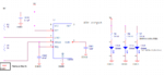
I want to drive 3 leds with 555 timer, frequency 4Hz.
I drive it with 9V.
The leds are 1.8V@2mA

I afraid it will not work properly.
I will more than happy from u guys to look at it and give your remarks..

Schematic is attached.

555 timer:
https://www.ti.com/lit/ds/symlink/ne555.pdf

555 timer.PNG
 

Re: 555 timer with three leds

Presently, you have shorted 555 out to 9V power supply and trigger input to ground. So yes, I won't work as is.

Perhaps you try a slight modification

555 timer.PNG
 
Re: 555 timer with three leds

hi,
Remove the 0v as per the image.
E
 

Attachments

  • 555 timer.PNG
    555 timer.PNG
    27.2 KB · Views: 84
Re: 555 timer with three leds

Thx a lot guys!

I removed the GND from the voltage divider, but did not touch 9V output.
it will work properly now?

thx a lot!!!
 

Re: 555 timer with three leds

9V to out short will still burn the 555. :sad:
 
Re: 555 timer with three leds

Thx a lot guys!

I removed the GND as u mention but not the 9V one the LEDs.
My drawing the esp1 said.

FvM, why to remove the 9V output?
Sorry if i ask idiot questions..

555 timer.PNG

Thx again!

- - - Updated - - -

I think i understand.

according to the datasheet, the output voltage will be 88%(approximately) from the VCC.
Hence, 9V to the output may burn the 555

i need to recalculate the series resistors(Leds resistors) according to 7.5-7.8V

Am i right?
 

Re: 555 timer with three leds

555 will be burned in LED off-state when it tries to pull the shorted output low with > 200 mA.

In any case the LEDs would be permanently on (if the power supply is strong enough).

Yes, the resistors should be corrected.
 
Re: 555 timer with three leds

You can drive the LEDs using a transistor driven by the output (pin 3 of 555) but the LEDs get less than 3mA each (I guess each LED can take at least 20mA) using the indicated series resistor. You can put the three LEDs in series (less than 6V total drop) and revise the series resistance and drive directly with the output (pin 3 of 555)
 

Thx u all!

I changing the schematic according to your notes and it look like this now.
555 timer 1.PNG

I draw another circuit to blinkung 2 LEDs alternately.
Is the schematic OK.
555 timer 2.PNG

Hope i don't annoying.

Thx you all :)
 

Hi,

At first sight according to a datasheet the second schematic design is also correct, but it looks on closer inspection like you need to choose between one load or another - if you think about what'll happen there a little bit. You can use the discharge pin for a second LED, if you do so with a little care. If your circuit doesn't work as planned, look for **broken link removed**, or 555 Timer traffic light schematics that use pin 7 as an LED "driver."
 

Attachments

  • Timer 555 lm TI.pdf
    1.3 MB · Views: 74

Status
Not open for further replies.

Part and Inventory Search

Welcome to EDABoard.com

Sponsor

Back
Top