Continue to Site

Welcome to EDAboard.com

Welcome to our site! EDAboard.com is an international Electronics Discussion Forum focused on EDA software, circuits, schematics, books, theory, papers, asic, pld, 8051, DSP, Network, RF, Analog Design, PCB, Service Manuals... and a whole lot more! To participate you need to register. Registration is free. Click here to register now.

[Moved] 20x4 lcd on and off problem

Status
Not open for further replies.
Re: 20x4 lcd gets dim when on

I concede that you can be facing all kinds of problems including the problem to arrange your results when starting electronics.

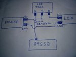
So please try to report your findings completely, including the suggested circuit schematics to help everybody to avoid talking on cross purposes.
 

Hi all...
i am sorry all if i have demotivated you all....
i am back with some of my problem.... i hope u might help me to get out of this...
Thia time i have used a MOSFET IRF9540. Gain to 5v source to lcd and drain to P3^5. and Gnded the Lcd.
now my problem is the MOSFET is not able to on the lcd whn i connect the drain to P3^5. But lcd gets on when i connect drain direct to 5v... ofcource it will..... Can anybody plz help me

- - - Updated - - -

I mean when i press the on button the lcd does not get on....

- - - Updated - - -

have also made my port 3 pins high.
 

Connect gate pin to the mcu p mosfet driver pin. Source pin to 5v supply and drain pin to the lcd module power supply pin.
I have assumed that you use same power supply source for both mcu and the lcd module.
Make sure that internal pullup is enable for gate driver pin. Otherwise use an external resister in between p mosfet gate and the source pin
 
What value of resistance should i use....
560 Ohms will work...????
have attached the circuit diagram....
is anything wrong with my circuit....
will this circuit work....????
 

Attachments

  • 1438458423971-1837431510.jpg
    1438458423971-1837431510.jpg
    667.6 KB · Views: 71

This is a silly idea, Why don't you just turn off the display with the display on/off command? when you do so the power consumption drops from typ 4ma to 150uA. Another consideration is that when you switch off the power supply all of the signal lines must be at 0V otherwise you will power the display through the signal lines with the potential problem of latch up when you restore the 5V.
 

Do not use 560Ohm.
Use like 1.5k for testing your circuit.
After you got it work calculate appropriate values.
 

Thanks a lot duresh.....
Ur ideas made my work complete... i have used 1k resistance and it is working absolutely fine...

@pjmelect. yes i have done it using a on/off command... but to execute this command i have to use a MOSFET.... i have even tested the current across the lcd after i shut down the lcd. it shows me 0 current and also nearly 0.1 - 0.15 volt.
 

You need to consider what pjmelect has mentioned.
"Another consideration is that when you switch off the power supply all of the signal lines must be at 0V otherwise you will power the display through the signal lines with the potential problem of latch up when you restore the 5V.
 

I would also add, the IRF9540, with a maximum VDS = -100V and ID = -19A, is beyond overkill. :shock:

After all, you are driving a 4mA max LCD, not a 10A motor. The IRF9540 would be beyond overkill for even driving the backlight at ~150mA max, let alone a 4mA device.

I hope this was only proof of concept, there are plenty of P-channel MOSFETs available in TO-92, SOT, etc., packages with specs more inline with driving a max 4mA device.


BigDog
 

Hi,

The now used solution was already given with post #15.....

I don't see the need for a gate resistor here.

A benefit could be a RC (to drain) combination for soft switch ON.

Klaus
 

@Klaus.... if i dont add the resistor between gate and source..... the the lcd is not getting switched off.... so in that case i have to add a resistor....

- - - Updated - - -

@bigdogguru.... yes you are right.... but as i told i am new with the MOSFET part.... i was not aware of it of how to use and it functionality.... and also gone througg the datasheet.... but did not understood anything.... so in that case i just made it a try... and all it worked fine....
But will it create any problem or will work fine....????
Thanks a lot u all....

- - - Updated - - -

to make the power supply of all the signal lines 0V.... shoud i low the port....
 

Hi,

@Klaus.... if i dont add the resistor between gate and source..... the the lcd is not getting switched off.... so in that case i have to add a resistor....
It must switch off.
Maybe occasionally you don't use the same supply voltage for both ucontroller and LCD,
or you switch the port to 'high ohmic' instead of 'high'.

to make the power supply of all the signal lines 0V.... shoud i low the port....
It has nothing to do with 'power supply'
Yes, as I already mentioned about 30 posts ago: switch signal lines to low during power down.

Klaus
 

i am using the same power supply for both MCR and lcd....
Actually i have a source volt of 7.4v 2200Ma Battery... and attached lm7805, 5v voltage regulator and connected my MCR and lcd to the output of lm7805.
 

Actually i have a source volt of 7.4v 2200Ma Battery... and attached lm7805, 5v voltage regulator and connected my MCR and lcd to the output of lm7805.

Finally, a tidbit of information critical to the overall system design.

Actually, this has been a major issue I've had with this thread since it's inception, not enough design and application specifics, which has also been voiced by FvM and other participates of this thread.

You've went to a lot of effort to save at most 4mA, in reality probably closer to 2mA, by powering down the LCD, however up until now, have made no mention of actual power source and regulator specifications, other than briefly mentioning it was a battery of some sorts, not to mention what steps have been taken to conserve power with the microcontroller. Both of which could likely far exceed the savings of 2mA to 4mA by powering down the LCD.

When attempt to conserve power, linear voltage regulators and batteries, are typically not a good mix, particularly when the linear voltage regulator has a relatively high Dropout Voltage, like the 78xx series.

Where Dropout Voltage is defined as, the minimum voltage drop from input to output of the voltage regulator required to maintain the specified level of voltage regulation. Dropout Voltage becomes critical when calculating power efficiency as shown below.

Linear voltage regulators are overall inherently inefficient, in comparison to switch mode techniques, and this inefficiency is largely due to the required Dropout Voltage.

Efficiency, of any power regulator, is defined as:

Efficiency = Po/Pi × 100% = (Vo × lo)/(Vi × Ii) × 100%,

where in the case of a linear voltage regulator, Ii~Io, which simplifies the equation to:

Efficiency = Vo/Vi × 100%, where Vi - Vo >= Dropout Voltage for specified regulation to be maintained

The Power Loss is approximately:

Power Loss ~ (Vi - Vo) x Ii or a minimum of (Dropout Voltage) x Ii during normal operating specifications.

For example, with the battery fully charged and with the 7805 drawing/supplying 100mA:

Power Loss ~ (7.4V - 5.0V) x 100mA = 240mW, primarily dissipated as heat

In comparison, the power consumption of the LCD:

Maximum Power Loss ~ 5.0V x 4mA = 20mW, in reality more in the range of 5mW to 10mW is typical.


Consider effort underwent to save, at most, 20mW, in comparison to the 240mW expended as heat, do you get the picture?


Also note, with a nominal Dropout Voltage of the 7805 at 2V, once the battery discharges to a level of below 7.0V, the 7805 can no longer maintain its specified level of voltage regulation.

At the very least, a linear voltage regulator with a Low Dropout Voltage (LDO) should be substitued for the 7805 and if greater efficiency is sought a switch mode regulator, like a buck topology, should be considered. Switch mode voltage regulators, unlike their linear counterparts can reach efficiency levels in the 90% range.

As I indicated, you still have not mentioned what steps/techniques you taken to conserve power at the microcontroller, which also would also likely exceed the savings of 2mA/4mA by powering down the LCD. Typically, putting the microcontroller to sleep between tasks, can achieve a surprising level of power conservation.


yes you are right.... but as i told i am new with the MOSFET part.... i was not aware of it of how to use and it functionality.... and also gone througg the datasheet.... but did not understood anything.... so in that case i just made it a try... and all it worked fine....
But will it create any problem or will work fine....????

The answer to your question depends largely on whether or not this is a hobby project, i.e., educational experience, or is the ultimate goal to produce and market your design as a commercial product. If the latter, then by all means use what is available to you, however if eventually the goal is to produce and market your design as commercial product, certainly choosing a P-channel MOSFET more suited to the task would be prudent and far more economical.

I would suggest, now that you've had some experience working with these devices, to spend two or three dollars and purchase a nice assortment of BJTs and MOSFETs of the smaller variety, they will come in handy and the small devices are a fraction of the cost of a single IRF9540. An assortment of BJTs and MOSFETs should be considered a standard staple, just as an assortment of resistors, capacitors and crystals.

I would urge you, as FvM and others have previously, to post a fully and detailed description of your design's purpose, required tasks, along with a schematic or at least a block diagram, rather than continuing to occasionally dribble out a tidbit or two. Doing so will not only aid those attempting to render advice, but would also help organize your thoughts and design.


BigDog
 
  • Like
Reactions: Duresh

    Duresh

    Points: 2
    Helpful Answer Positive Rating
Sorry for that....
actually i have also connected a 6v dc motor to it.... it operates with the keypress from the keypad.... if 1 ia pressed from keypad the motor starts rotating and again if 2 is presses ita gets stoped..... so in that case to drive a 6v dc motor i had to use a 7.4v battery. battery is directly connected to motor driver and input of driver to MCR. so to drop voltage from 7.4v to 5v for mcrr and lcd.... i have used a 7805 IC.
as u said u would prefer me to use buck topology insteas of 7805.... what is exactly a buck topology.... and how it is used.

- - - Updated - - -

what if i use LM317...????
will it work....????
 

Help me guys.....
my battery gets drained in 10-12 hours....
let me clear my concepts.
I have made a project in which the Lcd should turn on and off on keypress and also connected a 6v dc motor which runs clockwise and anticlockwise on the keypress.
I have connected a 7.4v battery to input of 7805 and output 5v from 7805 is connected to 89S52 and IRF 9805 Mosfet to on and off the Lcd.
Circuit Diagram.
Port 1 of MCR to lcd, Port 2 to keypad, port 3^3 and 3^4 to L293D motor driver to control the 6v DC motor. port 3^5 to IRF9805 Mosfet Gate pin.MOSFET source pin to direct 5v and drain pin to lcd. 1k resistance bwtween gate and source.
Code.
At initial stage have kwpt the lcd off.
P3^5=0xff; P1=0xff.
on keypress the lcd goes on.
P3^5=0x00; P1=0x00.
on and off function works perfectly... but when i keep my lcd off.... and also all the signal pins low... then why my battery gets drained in 10- 12 hours.
is anything wrong have i done....
please guide me....
 

A picture is (would be) worth a thousand words...

No idea how you manage to consume 150 to 200 mA (you claimed to have a 2200 mAh battery). I'm accustomed to use a multimeter to find out where the current flows.
 

i have found that the signal lines(port 1) of lcd are still powered up even if i off the lcd and have also high the pins of lcd at the time when lcd is off.... and also power pins of LCD shows me 1.32v....
can anybody plzz help me.... how to make the pins to 0v
 

What are the current requirements of your 6VDC motor? Do you have a datasheet or model number available?

An LDO linear voltage regulator or buck switch mode voltage regulator would be a far better choice.

Many Low Dropout (LDO) voltage regulator have a DO Voltage ranging from 1V a few tenths of a volt, versus the 7805's 2V DO. Is your battery pack a LiPo?

You need to examine the discharge curve of your particular battery, for example most 7.4V LiPo batteries discharge to about 6V where there is a knee and the current drops off sharply. You would also need to consider the particulars of your battery, as some recommend discharging only down to a specific voltage level.

Currently, the 7805, which has a DO of 2V, can sustain voltage regulation only until your battery discharges to 7V, after that you are SOL.

Substituting an LDO voltage regular would certainly help matters in regards to the voltage DO, however employing either a dual output switch mode buck voltage regulator or two single output buck voltage regulators would not only alleviate the voltage DO issue for the most part, the buck voltage regulators are far more efficient and would help extend the battery duration between charges.

Also, you never indicated whether or not you are putting the microcontroller to sleep between tasks, which can dramatically reduce it's power consumption.


BigDog
 

Status
Not open for further replies.

Similar threads

Part and Inventory Search

Welcome to EDABoard.com

Sponsor

Back
Top