Continue to Site

Welcome to EDAboard.com

Welcome to our site! EDAboard.com is an international Electronics Discussion Forum focused on EDA software, circuits, schematics, books, theory, papers, asic, pld, 8051, DSP, Network, RF, Analog Design, PCB, Service Manuals... and a whole lot more! To participate you need to register. Registration is free. Click here to register now.

MOSI and MISO on AT89S52

Status
Not open for further replies.

bianchi77

Advanced Member level 4
Joined
Jun 11, 2009
Messages
1,313
Helped
21
Reputation
44
Reaction score
20
Trophy points
1,318
Location
California
Activity points
9,442
Guys,

How can I use MOSI and MISO at 89S52 ? can I use serial port from computer, directly connected to these pins ? Any example codes for this function ?

Thanks a bunch
 

MOSI MISO SCK are for SPI ...
To communicate with PC, we use the UART interface in microcontroller. (TXD RXD). You should not directly connect those to serial port of PC because it may be RS232 or equivalent...
Its voltage range is high. So you need to use a voltage level converter like MAX232 in between....
If you need to just receive data send from the PC, then there is no need of a MAX232. A simple transistor inverter will do the job....

**broken link removed**
Atmel AVR & AT89S52 Tutorial Kit
 

How can I use MOSI and MISO at 89S52 ?

What is the intend use, programming the devices FLASH memory? The MISO, MOSI and SCK lines form a SPI interface which can be used for In System Programming (ISP) as well as a standard SPI interface to SPI peripheral devices.

Reference: AT89S52 Datasheet, Section: 19. Programming the Flash – Serial Mode & 20. Serial Programming Algorithm, pg 22

19. Programming the Flash – Serial Mode

The Code memory array can be programmed using the serial ISP interface while RST is pulled to VCC.
The serial interface consists of pins SCK, MOSI (input) and MISO (output). After RST is set high,
the Programming Enable instruction needs to be executed first before other operations can be
executed. Before a reprogramming sequence can occur, a Chip Erase operation is required.

The Chip Erase operation turns the content of every memory location in the Code array into
FFH.

Either an external system clock can be supplied at pin XTAL1 or a crystal needs to be connected
across pins XTAL1 and XTAL2. The maximum serial clock (SCK) frequency should be less than
1/16 of the crystal frequency. With a 33 MHz oscillator clock, the maximum SCK frequency is
2 MHz.

20. Serial Programming Algorithm

To program and verify the AT89S52 in the serial programming mode, the following sequence is
recommended:
1. Power-up sequence:
a. Apply power between VCC and GND pins. b. Set RST pin to “H”.
If a crystal is not connected across pins XTAL1 and XTAL2, apply a 3 MHz to 33 MHz clock to
XTAL1 pin and wait for at least 10 milliseconds.

2. Enable serial programming by sending the Programming Enable serial instruction to pin
MOSI/P1.5. The frequency of the shift clock supplied at pin SCK/P1.7 needs to be less than the CPU
clock at XTAL1 divided by 16.
3. The Code array is programmed one byte at a time in either the Byte or Page mode. The write
cycle is self-timed and typically takes less than 0.5 ms at 5V.
4. Any memory location can be verified by using the Read instruction which returns the content at
the selected address at serial output MISO/P1.6.
5. At the end of a programming session, RST can be set low to commence normal device operation.
Power-off sequence (if needed):

1. Set XTAL1 to “L” (if a crystal is not used).
2. Set RST to “L”.
3. Turn VCC power off.
Data Polling: The Data Polling feature is also available in the serial mode. In this mode, during a
write cycle an attempted read of the last byte written will result in the complement of the MSB
of the serial output byte on MISO.

Successful programming of the devices FLASH memory requires driving the interface at the appropriate levels and implementing the aforementioned programming algorithm.

While it is possible to implement a hardware programmer for the AT89S52, an easier route is to purchase a "canned" programmer compatible with this device, like an AVRisp or any of the numerous aftermarket options, like the USBasp. Search the forum for alternatives.


can I use serial port from computer, directly connected to these pins ?

Not unless you wish to damage the AT89S52, the PC RS-232 Serial Port or both. The RS-232 Serial Port has relatively high voltage levels of a positive and negative polarity. The signalling methods are also not compatible.


Any example codes for this function ?

If you intend on using the AT89S52's SPI interface with SPI peripheral devices, study the following examples:

AT89S8252 Primer - Section: Serial Peripheral Interface (SPI), pg 8

Atmel Appnote: SPI Program Examples

BigDog
 

While it is possible to implement a hardware programmer for the AT89S52, an easier route is to purchase a "canned" programmer compatible with this device, like an AVRisp or any of the numerous aftermarket options, like the USBasp. Search the forum for alternatives.
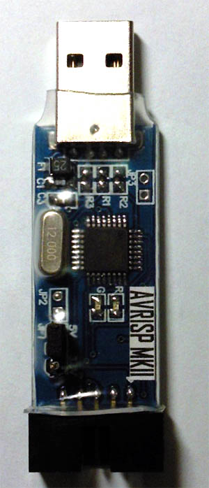
Like this one ?
ispdownloader.jpg
 

Like this one ?
ispdownloader.jpg

Possibly. However, without a link to the manufactures or sellers website, it is hard to state with certainty from only a photo.

The photo does resemble an AVRisp clone that has been posted numerous times in this forum.

BigDog
 
  • Like
Reactions: IanP

    IanP

    Points: 2
    Helpful Answer Positive Rating
Like this one ..
Do you guys have a code or a driver to use this device ?
I have the hardware, but no idea yet on how to use it correctly,
I think I'm gonna need a driver to brigde this device and window (OS)..
before I can connect into my AT89S52
 

You can use a AVRisp mkII with the STK500.exe application to program the both the AT89S51 and AT89S52, as well as numerous AVRs.

The STK500 software is included in the AVRStudio Software Package or downloadable directly from the ATMEL website:

ATMEL AVRISP mkII


BigDog
 
Status
Not open for further replies.

Part and Inventory Search

Welcome to EDABoard.com

Sponsor

Back
Top