Continue to Site

Welcome to EDAboard.com

Welcome to our site! EDAboard.com is an international Electronics Discussion Forum focused on EDA software, circuits, schematics, books, theory, papers, asic, pld, 8051, DSP, Network, RF, Analog Design, PCB, Service Manuals... and a whole lot more! To participate you need to register. Registration is free. Click here to register now.

Mosfet or Transistor to use with Large 7 Segment Displays

Status
Not open for further replies.

asking

Full Member level 5
Joined
Sep 21, 2010
Messages
279
Helped
6
Reputation
12
Reaction score
6
Trophy points
1,298
Activity points
3,377
Hello,

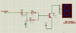
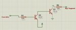
Transistor or Mosfet to be used with 7 Segment Multiplexing ? i want to multiplex 2.3" 4 7-segment Displays.... ? which would be the faster in real time so there's no lag in display....?
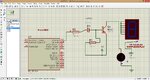
 

Both BJTs and MOSFETs are much faster then the multiplexing frequency: <microseconds vs. miliseconds ...
:wink:
IanP
 

Then why my displays are not working ? Please check the attached circuit...it shows 8888 while in small display it works perfect...without transistors..

please check the pdf file attached...and please let me know where i am wrong..
 

Attachments

  • Large 7 Segment Display Circuit.pdf
    13.4 KB · Views: 225

your circuit look ok but what i am suspecting is the current driven the display is not sufficient,so you need to buffer the signal coming out from the pic, you can use CD4050 i think your problem will be solved.
 

Do it is related something...to Putting 10K resistor between Emitter-Base Junction of TIP 127 ? or else i will try your method..putting CD4050
 

using 10k resistor between base-emiter you are only pulling down the base to ground and that not the problem,the problem is insufficient current to drive the display.
 

So you mean to say...take output from pic port B and give it to CD4050 and then take output from CD4050 and give it to Base of TIP127 via 10K Resistor right ? I did it but no success....still 8888 on 4 displays
 

No dont use 10k in series to the base use 470ohms to the base.
 

Your problem is the segment driver transistors. To turn them off you need to raise the base voltage until it is at or close to 12V (the emitter voltage) and you can't do that with a 5V signal source. They are always conducting, that's why you see all segments turned on. The solution is to use a voltage translating buffer (CD4050 should work) or else another transistor between the MCU and TIP122 to rise it's base voltage when 'off'.

Brian.
 
  • Like
Reactions: asking

    asking

    Points: 2
    Helpful Answer Positive Rating
Your problem is the segment driver transistors. To turn them off you need to raise the base voltage until it is at or close to 12V (the emitter voltage) and you can't do that with a 5V signal source. They are always conducting, that's why you see all segments turned on. The solution is to use a voltage translating buffer (CD4050 should work) or else another transistor between the MCU and TIP122 to rise it's base voltage when 'off'.

Brian.

Good catch Brian.

Strangely enough the OP states that this worked without BJT's on a smaller 7-seg display, so it's not clear where the +12v came from. Also, why would you need to change a simpler circuit for this larger display -- is the current required really that much larger ? No mention of actual display's actual specs of course.

And lastly - even with the suggested mods, imho the OP will have to adjust his code since now the BJT's will be doing a logic inversion. Plus I see no current limiting resistors -- i'm surprised nothing has blown.

cheers!
 

Displays are 2.3" Inch and power rating of 150-200ma and 12Volt...for each single display...VT23CCSG Model no. of display sorry i did no provided information before.

- - - Updated - - -

Thanks for suggestion....but do i have to use CD4050 only for Port A (driving transistors) or also for Porb B (data transistors) ?
 

I Did place connection of Driving Transistors through CD4050 now the counter is running but some of the 4 display one by one gets off and all have 8 8 8 8 so i think i need to put CD4050 between Port B (7 segment data) too..... ?

- - - Updated - - -

also...please check m right or not about connection ?.... MCU Port A ---->>> CD4050 ----->>>1K Resistor---->>>TIP122 Base. Is this right ?
 

Yes.

The CD4050 must run from the 12V supply. It isn't the ideal solution, a single transistor inverter in each of the segment drivers would be better. As pointed out earlier you must also fit a current limiting resistor in each segment line between the TIP and the LED module itslef or it may burn out.

The digit drives are OK, to turn the transistors off all you have to do is remove the voltage on their base pins by driving the MCU outputs low, to turn them on you drive the MCU pin high which is more voltage than the Vbe of the transistors so they draw base current and conduct LED to enable LED digit current.

The segment drivers are the problem, to turn them off you have to make the voltage between the base and emitter pins less than Vbe which is around 1.5V. As the emitters are tied to 12V, you have to make the base voltage higher than (12 - 1.5) 10.5V and you obviously can't do that directly from the MCU when it only runs on a 5V supply.

The simplest electrical solution is to wire single low power transistors in each segment drive from the MCU, they should be wired exactly like the digit drive transistors except they do not have to be darlington types. The collector of these goes to the existing Q5-Q11 bases through say a 10K resistor and across each base - emitter of Q5-Q11 you wire another 10K resistor. The drawback to this is the additional transistor inverts the signal so when the digit should be off it is on and vice versa. This is easy to fix in software if you have the source code, you just invert the states of the segment drive signals.

Brian.
 

no success in using CD4050 supplying 12v...i have taken all output from MCU to CD4050 and then to Display driver transistors..now all displays off and nothing...sometimes flickers comes and goes.....i think i need to use BC547 and BC557 for display driver transistors... ?
 

Try this driver circuit:
SegDriver.png

But note the segment drive signals will be inverted. You can use 1K resistors although they can be higher.

Brian.
 

Brian,

Case 1:

I read the Datasheet of TIP122 and its Base Current Ib is 100mA. Here's the problem. Our PIC Microcontroller is capable of providing maximum 40-60mA and when its frequency is higher average current is lower.... so i was thinking to use BC557 and take input at base from PIC MCU and emitter to +12V and collector (150-200mA) to the base of Existing TIP122 ? what do u think ? this will delay our response ? according to me it should not delay as all things are too fast... please suggest.....

OR

Case 2:

Can i use IRFZ44N i read its datasheet it requires min 2.0v and maximum 4.0v ? our PIC Avg output voltage would be 4-5V so will it be ok ?
 

Attachments

  • bc557_tip122.jpg
    bc557_tip122.jpg
    70.7 KB · Views: 191

Both wrong!

Case 1: the MAXIMUM rated base current for the TIP122 is 120mA, the actual current it needs is Ic/HFE, in other words, the current drawn by the LED segment divided by at least 1,000. This will be less than 1mA. However the problem is not the current, it's the voltage needed to turn the TIP off. When the segment is not lit up, the base voltage of the TIP must be close to it's emitter voltage. The emitter is tied to 12V so you have to lift the base up to that voltage too and it's impossible to do that directly from a PIC. The schematic you show is not only incorrect but it sinks current to ground, you need to source it from the 12V rail.

Case 2: Still the same problem, you don't need 0V - 5V, you need 12V - 10.5V.

There is a 'dirty' solution to your problem which will work but experts will frown upon it. Connect the bases of Q5 - Q11 to +12V through a 1K resistor and connect each base to the PIC through a 1K resistor and 8.2V Zener diode. When the PIC output is low, the transistor will conduct, when it's high the transistor will turn off and the Zener will protect the PIC output from going over-voltage. Connect the Zener cathode (+) side toward the transistor.

Brian.
 

ok Brian, i will try your Zener Diode method.....

Actually i yesterday i was testing switching of BC547(NPN) and BC557 (PNP), interesting thing i found was NPN Transistor is switching with the same frequency as PIC. But its not the case with PNP Transistor. PNP Was not switching fully off and i can see low flickering of the display with PNP. Means PNP is not going fully switch off condition....means PNP Part of our circuit is the culprit and it remains on thats why i was seeing... 8888 on my four displays

is there any proper way of driving PNP resistor directly from MCU ?
 

Brian,

Please check the circuit i have prepared...you mean this way ? if not..please post the correct circuit for Data Pins (Port B) of 7 Segment....PNP TIP 127 Transistor.

- - - Updated - - -

OK THIS CIRCUIT SEEMS TO BE BLINKING LED WITH MCU DUTY CYCLE.....ONLY DIODE WAS ABLE TO DRIVE THE LED AND I DID MODIFICATION AS PER YOUR SUGGESTION. PLEASE CHECK THE ATTACHED 2ND IMAGE...( ZENER DIODE CIRCUIT 1.jpg)

it works :) i checked..... now m applying it to my already made circuit then lets see :)

- - - Updated - - -

Ok Problem is solved just by placing the Zener between the Resistor and Base of Q5-Q11 :) PNP Transistors. Thanks all for support.
 

Attachments

  • ZENER DIODE CIRCUIT.jpg
    ZENER DIODE CIRCUIT.jpg
    108.3 KB · Views: 226
  • ZENER DIODE CIRCUIT 1.jpg
    ZENER DIODE CIRCUIT 1.jpg
    291.9 KB · Views: 326
Last edited:

I'm glad it worked.

Your second schematic isn't quite right, you have a link between both ends of the resistors instead of only at the base pin.

The drawback to this kind of driver is it can't switrch the segments off or on as quickly as the two transistor method so there is a risk of 'ghosting' and also the PIC output has to sink some current when in the high logic state which it isn't realy designed to do. It's internal protection diodes should hopefully keep it safe but be careful if a situation could arise where the 12V was present but the PICs 5V supply was missing because it could cause damage if the 5V was restored.

Brian.
 

Status
Not open for further replies.

Part and Inventory Search

Welcome to EDABoard.com

Sponsor

Back
Top