Continue to Site

Welcome to EDAboard.com

Welcome to our site! EDAboard.com is an international Electronics Discussion Forum focused on EDA software, circuits, schematics, books, theory, papers, asic, pld, 8051, DSP, Network, RF, Analog Design, PCB, Service Manuals... and a whole lot more! To participate you need to register. Registration is free. Click here to register now.

MOSfet-driver question

Status
Not open for further replies.

Wamor

Junior Member level 2
Joined
Jun 16, 2009
Messages
24
Helped
0
Reputation
0
Reaction score
0
Trophy points
1,281
Activity points
1,491
Hello,

I am using a IR4426 mosfet-driver to switch a IRFR3910 mosfet.
The IR4426 mosfet-driver has a Io+/- of 1.5A.
The IRFR3910 mosfet has a Qg of 44nC (Qgs = 6.2nC and Qgd = 21nC).
If I do not use any gate resistor I learned that I can calculate the mosfet-switch-on time by the following formula: t = Qg / Io which gives me a switch-on time of 29.3ns. Is this correct?
Is the IR4426 always supplying 1.5A also when I use a mosfet which doesn't require a current of 1.5A?
What will be the influence of a gate-resistor with regards to the switch-on time?
How do I calculate the correct gate-resistor.

Thank you and best regards
 

You'll use a gate resistor, if you want (or need for some reason) to slow down switching.

I don't agree with the switching time calculation. The most interesting parameter (e.g for switching losses) is the rise time, basically corresponding to the miller charge. For the switch-on time, the Qgs part up to the plateau in the Vgs(Q) diagram adds. But the total gate charge doesn't count for switch-on.

The effective gate current with a gate resistor will depend on the plateau voltage (Vgs,on) and the driver voltage.
 

    V

    Points: 2
    Helpful Answer Positive Rating
The gate of the mosfet appears to the driver as a capacitor that must be charged to the threshold voltage to turn the device on. So the more current you can supply to charge/discharge the capacitor, the faster you can switch it on and off.

You can get an estimate of the turn on time by subtracting the mosfet turn on voltage from the drive voltage. Divide this value by the gate resistor to get the average charge current.
The turn on time is the total gate charge in nana Coulombs divded by the current in Amps, this gives the answer in nS.
Example;
Drive voltage 12 Volts. Mosfet threshhold voltage, 1.5 Volts. Resistor 10 Ohms.
Charge current = (12 - 1.5) / 10 = 1.05 Amps;
Turn on time = Total gate charge divided by charge current = 44 / 1.05 = 41.9 nS.
Due to the small value of capacitance involved, other factors come into play such as component layout.
The normal procedure is to calculate the values then verify the actual performance by measuring the switch on/off and rise/fall times using a scope.

Without a series gate resistor, the peak charge current from the driver may be higher than the spec, as there is no control over it???
 
Last edited:

    V

    Points: 2
    Helpful Answer Positive Rating
Turn on time = Total gate charge divided by charge current = 44 / 1.05 = 41.9 nS.
Total gate charge is including the charge supplied after the MOSFET is turned on. Thus the calculation overestimates the turn-on time. In contrast, the gate charge part
for Vgs > Vgs,thr counts for turn-off.
 

    V

    Points: 2
    Helpful Answer Positive Rating
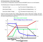
This is from the link above

Mosfer_gate_charge.jpg

I have added colors for easier reading,
you can easily see that the output current is maximized and the voltage drop is starting to drop long before the Gate total charge point.

Alex
 
Last edited:

    V

    Points: 2
    Helpful Answer Positive Rating
Thanks for linking the Fairchild application note. It's explaining things very clear.
 

Status
Not open for further replies.

Similar threads

Part and Inventory Search

Welcome to EDABoard.com

Sponsor

Back
Top