Continue to Site

Welcome to EDAboard.com

Welcome to our site! EDAboard.com is an international Electronics Discussion Forum focused on EDA software, circuits, schematics, books, theory, papers, asic, pld, 8051, DSP, Network, RF, Analog Design, PCB, Service Manuals... and a whole lot more! To participate you need to register. Registration is free. Click here to register now.

Monopole antenna design using HFSS

Status
Not open for further replies.

bijus

Member level 1
Joined
Apr 11, 2013
Messages
34
Helped
0
Reputation
0
Reaction score
0
Trophy points
1,286
Location
India
Activity points
1,534
Dear all,

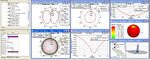
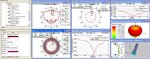
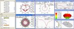
I am a beginner in this field HFSS. I would like to design a monopole antenna in HFSS. I have completed the preliminary stage up to my knowledge and i have some doubts about the measurements and report generation.

I tried the design of monopole using both lump port and wave port. Pls suggest which is good. Attached both simulation files and test results.

The VSWR is ok and provided the details of the test report I have with me.
In HFSS, i had added the far-field option for generating reports.

The elevation pattern is seems good. Now i want to know how we will measure the H Plane pattern (Omni Directional) / how we will generate the report of H Plane Pattern.
Pls help me to measure/see the H plane Pattern and also the exact absolute gain figure. Also pls advise the steps to be followed to measure the same.

Your valuable suggestions requested....

Pls Help.....

T&R
 

Attachments

  • Monopole.zip
    197.9 KB · Views: 296

In "Results" --> "Create Far Fields Report" --> "Radiation Pattern" you have do change the "Primary Sweep" from Theta (V) to Phi (H).
 

Dear tes87,

Thanks for your valuable suggestion. Now i want to know the gain of my antenna. for measuring gain which angle to be measured (eg: theta 90degree, Theta 180 degree....) in the result Theta 310 degree shows maximum value(1.8 dB) pls correct me, if i am wrong .... i am attaching the results with me ...pls help

T&R
 

Attachments

  • Hplane Pattern -1.jpg
    Hplane Pattern -1.jpg
    119.4 KB · Views: 168

you can look at the 3D Polar Plot (Far Fields Report) to have a overview of the complete farfield. There you can also see the vectors phi and theta. In theorie the highest gain for a monopole are by theta = 90°, but this depend on your model (z,y,x axis). Take a look at the 3d report to decide the right theta. In the "Radiation Pattern" Report you can switch to "families" and disable the other theta solutions, so you see only once in the graph.
 

Re: Monopole antenna design using HFSS _antenna gain with respect to ground plan

Here I am attaching three different test results of a monopole antenna in different ground planes.

Monopole antenna resonating at around 2 GHz. By increasing the ground plane diameter the gain of the antenna is increasing.

As per my results says, gain of 2 GHz antenna
@ 60mm GP is 1.99 dB,
@1 Feet GP is 4.85 dB &
@ 3 Feet GP is 6.15 dB.

Is it correct?
Will antenna Gain varies with respect to the ground plane?
If yes what will be the optimum ground plane in this frequency?
How it calculate?

Pls correct me if I am wrong?

T&R

Biju
 

Attachments

  • Quarter wave monopole -60 mm GP..jpg
    Quarter wave monopole -60 mm GP..jpg
    111.9 KB · Views: 218
  • Quarter wave monopole - 1feet GP..jpg
    Quarter wave monopole - 1feet GP..jpg
    107.1 KB · Views: 243
  • Quarter wave monopole - 3 feet GP.jpg
    Quarter wave monopole - 3 feet GP.jpg
    111.4 KB · Views: 197

Re: Monopole antenna design using HFSS _antenna gain with respect to ground plan

Here I am attaching three different test results of a monopole antenna in different ground planes.

Monopole antenna resonating at around 2 GHz. By increasing the ground plane diameter the gain of the antenna is increasing.

As per my results says, gain of 2 GHz antenna
@ 60mm GP is 1.99 dB,
@1 Feet GP is 4.85 dB &
@ 3 Feet GP is 6.15 dB.

Is it correct?
Will antenna Gain varies with respect to the ground plane?
Yes. Ground plane will definitely affect the results.

If yes what will be the optimum ground plane in this frequency?
Optimum in terms of what parameter? If you want maximum gain, then you theoretically need an infinite ground plane..

How it calculate?
For the upper hemisphere region, a monopole on an infinite ground plane is exactly the same case as a (twice-as-long) dipole without the ground plane. Any standard textbook should discuss this (Image theory). For a finite ground plane, it might be much more difficult to get closed form analytic solutions for radiated fields.

Pls correct me if I am wrong?

T&R

Biju

What is the length of your monopole ? If it is a quarter wavelength, then the max. gain should be ~5.1 dBi in the limiting case of very large ground plane.
 
Last edited:
Re: Monopole antenna design using HFSS _antenna gain with respect to ground plan

hi,

Thank you for the reply and details shared....

i am using quarter wave monopole antenna. the exact height of my antenna is 42 mm. (As per λ/4 @2GHz is 37.5mm).

As you said the max gain is ~5.1 dBi how is it calculated? or any specific gain chart is there? How we know that our design values are optimum? Pls share your valuable suggestions?

As per your advise the gain is ~5.1 in the larger Ground Plane. If so my design is having any problem? with 3 feet ground plane my gain is 6.15. I am attaching my design here. pls correct me if i am wrong....

Thanking You in advance..

Biju
 

Attachments

  • Monopole 2 GHz_Rev6 a_gp 3 feet gp.zip
    40.3 KB · Views: 224

Here is a old, but useful explanation on the topic: [ **broken link removed** ]

From figure 6, on this page: [ http://www.antenna-theory.com/antennas/dipole.php ], you can see the relationship between directivity and dipole length.

Also see this page: [ http://www.antenna-theory.com/antennas/monopole.php ]. The directivity of a monopole antenna is directly related to that of a dipole antenna. If the directivity of a dipole of length 2L has a directivity of D1 [decibels], then the directivity of a monopole antenna of length L will have a directivity of D1+3 [decibels].
 
Thank you for the valuable details shared.
We would like to have some more clarifications in this regard. In the details shared the monopole gain is defined as 5.17dBi (Gain of dipole +3dB or double the gain of dipole) considering an infinite ground plane. How could we define it over a finite ground plane, for example a 32 feet ground plane? Is there any nominal value or any calculation or any standard practice, something like absolute gain of monopole from 30-400 MHz defined in "MIL-DTL-85670C"


T&R
 

Attachments

  • 30-400.jpg
    30-400.jpg
    20.3 KB · Views: 135

Pls Help me to clear my doubt.....

Thank you in advance...
 

When it comes to the definition of gain in dBi, the reference is always considered as an ideal isotropic radiator. An isotropic radiator is fictional and cannot be realised in real life.

So, in practice, as mentioned in MIL-DTL-85670C, the antenna to be tested is compared against a 'standard reference' antenna. What that document mentions is how much gain is provided by the monopole (over ground) when it is being used as a standard/reference.

In your HFSS simulations, you do not have to worry about this reference antenna for comparing against. The software will directly give you the value for the gain.


Thank you very much for your valuable advise. As you mentioned, in HFSS software directly give us the value of gain. My question is that , how can we analyze that our design is correct. (in HFSS, the gain of the monopole vary by changing the ground plane diameter) Pls dont get irritated by asking the question again and again, because i am not getting the logic that to Analise the HFSS design is correct and the gain is maximum. pls share your valuable advise......
 

there are two different cases that you need to solve independently.

1. for the case of an infinite ground plane, you can set up the required option in the PerfE condition. the ground plane should extend all the way upto the edges of your airbox.

2. for the case of a finite ground plane, you should be include this entire block within the radiation boundary and leave sufficient* space between the finite ground plane and surrounding airbox boundary. (*sufficient = at least lambda/4 away at lowest operating frequency.)

You can refer the attachment with this post. I have an uploaded an example for the infinite, as well as finite ground plane simulation. In the first file, the infinite ground plane is in the theoretical limit. In the second file, you can modify the size of the ground plane and observe different results.

In both, you should be able to find a report of the radiation pattern with a marker indicating the max. gain obtained.

------------------------------------------------

how can you know whether your answer is correct ?
a. try to analytically solve for it (very difficult)
b. build an experimental prototype and measure it (comparatively easier)
 

Attachments

  • monopole.zip
    62.4 KB · Views: 167
there are two different cases that you need to solve independently.

1. for the case of an infinite ground plane, you can set up the required option in the PerfE condition. the ground plane should extend all the way upto the edges of your airbox.

2. for the case of a finite ground plane, you should be include this entire block within the radiation boundary and leave sufficient* space between the finite ground plane and surrounding airbox boundary. (*sufficient = at least lambda/4 away at lowest operating frequency.)

You can refer the attachment with this post. I have an uploaded an example for the infinite, as well as finite ground plane simulation. In the first file, the infinite ground plane is in the theoretical limit. In the second file, you can modify the size of the ground plane and observe different results.

In both, you should be able to find a report of the radiation pattern with a marker indicating the max. gain obtained.

------------------------------------------------

how can you know whether your answer is correct ?
a. try to analytically solve for it (very difficult)
b. build an experimental prototype and measure it (comparatively easier)


Thank you very much for your advise. and sorry for the delay. the two files that you sent to me is unable to open. it shows: "LineAxisRenderAttributre:1543: Value not valid." I am using HFSS Version 11.
Thanks for your kind cooperation and understanding......
 

Which version of HFSS are you using ?

I developed the two files based on the HFSS ADK, which I think works from HFSS v12 onwards.
 

Which version of HFSS are you using ?

I developed the two files based on the HFSS ADK, which I think works from HFSS v12 onwards.


Good Day~

I am using HFSS Version 11

Thanks & Regards
 

Try these two files then.
 

Attachments

  • monopole_2.zip
    66.3 KB · Views: 173

Status
Not open for further replies.

Part and Inventory Search

Welcome to EDABoard.com

Sponsor

Back
Top