Continue to Site

Welcome to EDAboard.com

Welcome to our site! EDAboard.com is an international Electronics Discussion Forum focused on EDA software, circuits, schematics, books, theory, papers, asic, pld, 8051, DSP, Network, RF, Analog Design, PCB, Service Manuals... and a whole lot more! To participate you need to register. Registration is free. Click here to register now.

Modifying a current limiter circuit for a higher voltage

Status
Not open for further replies.

boylesg

Advanced Member level 4
Joined
Jul 15, 2012
Messages
1,023
Helped
5
Reputation
10
Reaction score
6
Trophy points
1,318
Location
Epping, Victoria, Australia
Activity points
11,697
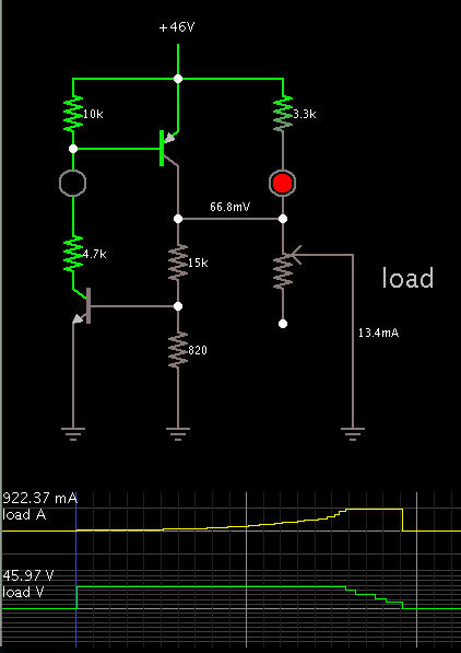
This circuit works really well in that you get a very sharp drop off in output voltage from Q1 at around 1% of 1k pot.....around 10R.
Up until that load the voltage remains very close to 15V before dropping off sharply until Q1 turns off entirely.


I am trying to modify the circuit to take 46V input and have the same characteristics or as close as possible to the 15V version.
What happens is that the output voltage of Q11 starts dropping slowly at around 7% of 1k pot.....so around 70R. As you reduce the pot below 7% the voltage continues to drop more gradually until Q11 turns off completely at around 1.5% or something like that.

I have tried setting all the resistor values such that, with the pot at 100%, the mA in each arm of the circuit are roughly the same as with the 15V version of the circuit and such that the voltage divider gives as close as possible to the same output voltage of around 2.16V. But that does not seem to work. I have also tried reducing the total resistance of the voltage divider so as it increase the base current of Q2 and keep it in saturation, but that doesn't seem to have any effect either.

Can anyone give me some pointers here as to how I might go about reproducing the sharp voltage drop off as occurs with the 15V version of the circuit above.
 

That's not really a good curent limiter design. Rather than limit the current it works on the principle of shutting down when the output is overloaded. It monitors the output voltage rather then the input current and shuts down when the voltage has been dragged to near zero by being overloaded. You can use it for limiting in that way but it's performance will be dependant on the exact characteristics of the transistors and the limiting action will depend on temperature. Using LEDs like that is also not a good idea and you may even see a change in output depending on lighting conditions!

A much safer way to do this is to place a resistor in series with the input to the pass transistor and monitor the voltage across it. That method really does give control over the current without adversely changing the voltage.

Brian.

Shutting down when the circuit is shorted is the functionality that I am really after here - I am not really interested in maintaining a constant current. It is meant to be in effect a re-settable fuse.

I thought the LEDs were simply being used as indicators in this circuit.

As far as I can tell all current limiters work by reducing the voltage in order to maintain a constant current/power output. Am I mistaken here?
 

I'm trying a simulation. I believe R35 (560 ohms) should be more like 10k.


Things start out with the load receiving power through transistor Q11.
Led #11 is on.

I reduce load resistance.

When the load draws more than 900 mA, I see a changeover starting to happen.

As I continue, the load transistor gets shut off. Led #11 is off. Led #4 is on.

Things stay that way, until I cause a reset by raising load resistance to 900 ohms, or remove it completely.

I haven't tried your modifications yet, but what is happening with the circuit below I have on my bread board is that the BD140 seems to fry a bit when I short the circuit - the hFE as measured by my multimeter falls by about 20 or so.

From then on, even with the load at max, LED4 remains half on and LED1 remains on as previously.

I can short the circuit again and LED4 still goes completely on and LED1 completely off.

So some how the limits of Q1 are being exceeded but I can't figure out how because I can't reproduce it in the simulation.
 

1.

It's likely that Q1 is getting overheated. That can alter its operating characteristics.
However it will require a sophisticated simulator to model heat-related behavior.

2.

A little more experimentation reveals that R33 needs to be tweaked to the right value, to get the desired range of operation. Try 1200 ohms.

R35 value is not nearly as critical.

Those changes seem to work a little better - I think the cut of range is a little tighter. Thanks.

Perhaps I should put a small heat sink on the real BD140.
 

Those changes seem to work a little better - I think the cut of range is a little tighter. Thanks.

Perhaps I should put a small heat sink on the real BD140.

Perhaps so. When the circuit-breaker action has just started, there is a point where Q1 is dropping so many volts (at 800 mA), that it must dissipate over 30 W of heat.
 

I swapped the BD140 for a SB1375(100V/3A/25W...or there abouts)

This reveals that Q11 does not shut down entirely when you short the circuit and it gets very hot, which is no doubt why the BD140 was failing.

When the circuit is shorted, both the LED remain on.

I measure about 5mA of current through the base of Q11 when the circuit is not shorted and this only drops to about 4mA when the circuit is shorted.

The values of R31, R33 and R35 don't seem to matter much.

Any more hints for me?

Could it be that this type of circuit just doesn't work for voltages over a certain value?
 

You need a comparator of some kind. If you don't want to use an op amp, U1 is cheap and small. Play around with this circuit. R1 sets the trip point at 1A. As shown outputs shuts down in under 20uS. Once tripped the load must be opened with S1 before it will start up again as a safety feature.
 

Attachments

  • 1A_lim.gif
    1A_lim.gif
    127.8 KB · Views: 131

You need a comparator of some kind. If you don't want to use an op amp, U1 is cheap and small. Play around with this circuit. R1 sets the trip point at 1A. As shown outputs shuts down in under 20uS. Once tripped the load must be opened with S1 before it will start up again as a safety feature.

OK thanks.

Interesting circuit but I am not familiar with TL431ACP at all. I found a datasheet but which application circuit exactly do you have it wired as here?

Why do you need to keep its cathode at or below 9.1V with the zener?

I actually do have some salvaged comparators that I could use. Do you have a version of this circuit that uses a comparator?

- - - Updated - - -

I am a little for familiar with using opamps and comparators so I think I can sort of guess how you would use a comparator in this situation.

Instead of monitoring the output current with the voltage divider and feeding this output voltage into the base of Q12, as I currently have, I would instead feed it into a comparator and the output of this would feed Q12. In so doing I would get a much more precise trip point I would think.

Does that sound roughly correct?
 

The TL431 should not have voltage above 36V applied. I used a common zener voltage of 9V. You could use 9V to say 27V if you want.

Yes, you could use a comparator that way. The TL431 is basically a comparator that turns on a transistor internally (between cathode and anode) if the sense voltage goes above the trip point. So, it functions as a shunt regulator.
 

I think I officially give up with the 46V version of this circuit because the simulator just doesn't seem to match what the real circuit is doing and it doesn't seem to matter what resistors I put in - the two LEDs remain stubbornly lit when I short it and the transistor heats up massively.

46V must exceed the limits of this circuit and it just isn't ever going to work and it is really not worth the effort of making the circuit more complicated with comparators.

46V will just have to rely on the fuse I have put in.
 

Do you need exactly 46V out? If you can afford to lose 0.7V or so, you can just limit the current at 1A.
 

You will never get it to reliably limit the current without anything to measure what the current actually is. You can imagine your circuit working like a relay coil across the output voltage with it's contacts in series with the incoming supply. It would normally connect the output and energize the coil but if you shorted it out, the coil voltage would be zero and the contacts would open. Using transistors you are making the BD140 pass current to sustain it's own bias. The only way to remove the bias is to short the output, in other words relying on the BD140 NOT to be able to cope with the load. Another analogy would be to keep a car engine at high revs and control your road speed with the brakes. It does work because the engine cannot cope with the increased drag but at the expense of overloading it and maybe damaging it.

You can try this, it isn't perfect but it "floats" at input voltage so it should work at any reasonable level:

7216519000_1363790614.jpg


Calculate RBIAS to allow the BD140 to conduct fully under more than your maximum current limit. A good starting value would be 330 Ohms.
Calculate RLIM so it drops 0.65V at the current you want to limit at. (R = 0.65 / I).

The theory is that when the current is low, the BD140 is fully conductive but when the limit is reached, the voltage dropped across RLIM makes the left transistor conduct and shunt the current away from the BD140 B-E junction, making it conduct less.

Brian.
 

"Calculate RBIAS to allow the BD140 to conduct fully under more than your maximum current limit. A good starting value would be 330 Ohms."

You have me rather confused with this brian because if the load draws more than my max current I want the BD140 to shut down rather than conduct fully.
 

No, RLIM sets the limiting current, what you have to ensure is the BD140 doesn't limit the current by itself. Ideally, it should be fully conducting all the time until the other transistor cuts it's bias current off. If you make RBIAS too large, the BD140 wont be able to deliver enough current and you will get a gradual roll-off of voltage as the load current increases. If you make RBIAS too small, the current in the first transistor may become larger than necessary. What you really want is for the BD140 to behave like a perfect switch, invisible to the current when turned on and completely isolating it when turned off.

Brian.
 

Status
Not open for further replies.

Part and Inventory Search

Welcome to EDABoard.com

Sponsor

Back
Top