Continue to Site

Welcome to EDAboard.com

Welcome to our site! EDAboard.com is an international Electronics Discussion Forum focused on EDA software, circuits, schematics, books, theory, papers, asic, pld, 8051, DSP, Network, RF, Analog Design, PCB, Service Manuals... and a whole lot more! To participate you need to register. Registration is free. Click here to register now.

Mixer isolation simulation need help

Status
Not open for further replies.

TerryADS

Full Member level 2
Joined
Oct 31, 2008
Messages
133
Helped
2
Reputation
4
Reaction score
2
Trophy points
1,298
Location
USA
Activity points
2,066
Hi friends,
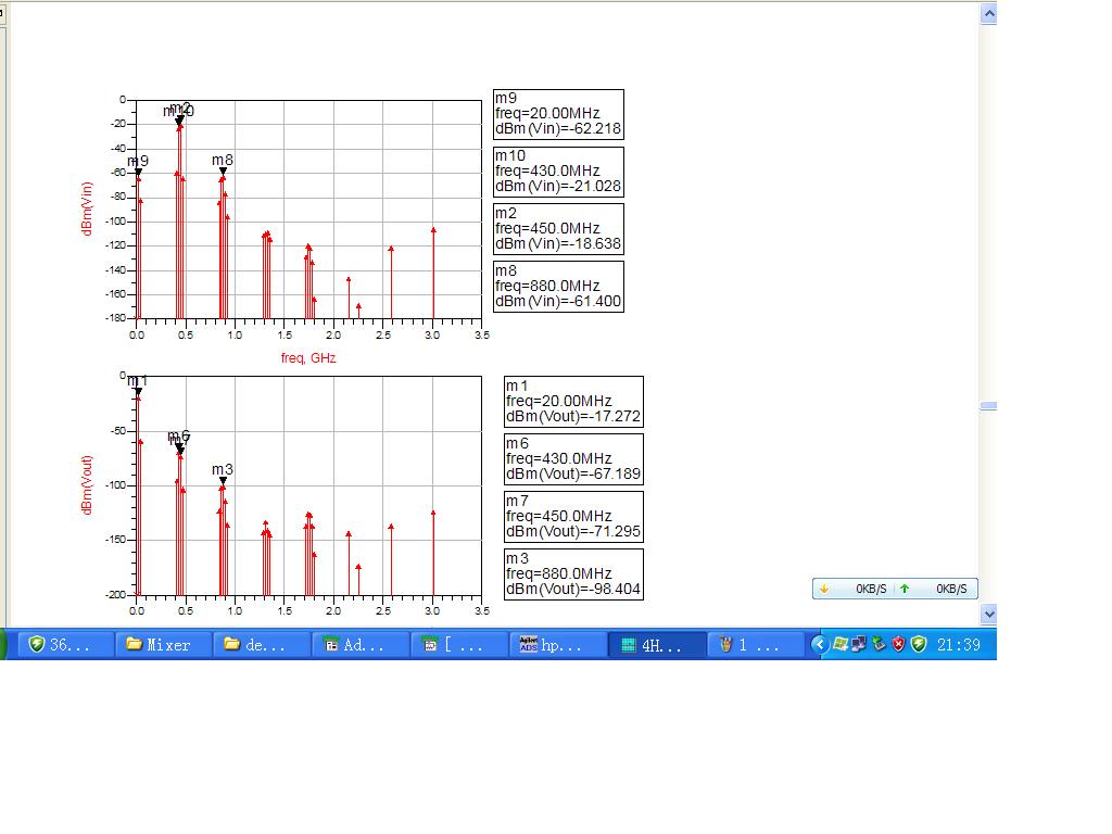
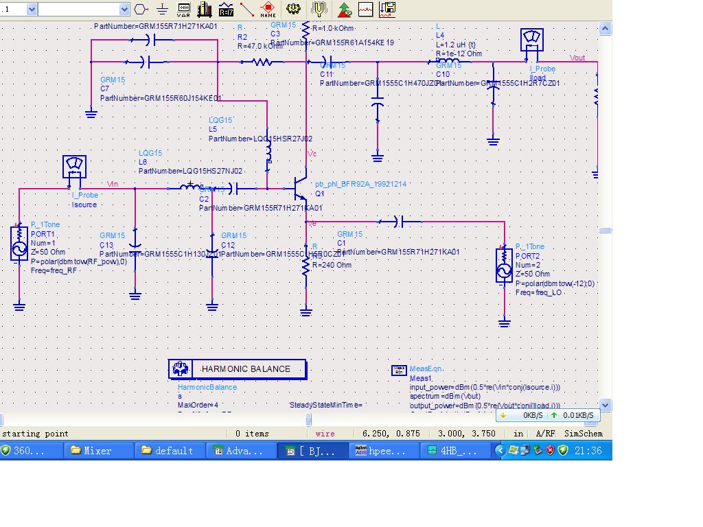
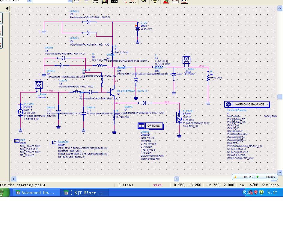
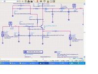
I simulated a mixer.I found the node"Vin" has more harmonic as bellow attached,what cause this case.and how to reject LO frequency from RF input port?What type filter i can remove LO frequency?
Thanks


You should post more information about your circuit, like the frequencies for Vin, Vout and LO.

From your graphics I can't tell which signal is input,output and LO because you didn't labeled it.
 

    TerryADS

    Points: 2
    Helpful Answer Positive Rating
Sorry that missed some information.now i attached the total schematic photo.
 

Well I had the same problem once. It's a typical frequency conversion: you want to convert a signal from an high frequency to a much lower frequency. The problem is that both your input frequency and LO frequency are very close (450MHz and 430 MHz) so it's very hard to eliminate the LO harmonics from the input because it would require a filter with a very high Q factor (5th order filter or more).

That's the reason why in most cases these kind of conversions are done in 2 or more steps. For example, using two conversions with same LO frequency:

1) Convert from 450 to 235 MHz using a 215 MHz LO

2) Convert from 235 to 20 MHz using a 215 MHz LO

As you can see, in this case, the LO frequency is well separated from both the input and output frequencies, making it easier to filter. Using the same LO frequency in both cases simplifies the circuit.

You probably don't want to completely change your circuit right? If that's the case I can't think of way of solving that problem, I'm sorry. Perhaps you can still use band-pass filters but don't expect much improvement. Using filters with ressonance can give you a nice filtering performance and that's how I solved in my case. However, that requires precise L and C components which are probably not available on the market. This means that you may not be able to implement the circuit in real life or, at least, it won't work as well.

Wish I could help more.
 

    TerryADS

    Points: 2
    Helpful Answer Positive Rating
Hey Terry,

I have been trying to design a pager that operates from 450-458MHz. The LO operates from 428.6MHz to 436.6MHz. One pager on the market I pullsed apart was using similar frequencies but they had a saw filter just prior to the first mixer. I recommend if necessary that you use a saw filter. A Common base amplifier will also provide good isolation between the output and input of the amp. But what sort of rejection of the LO do you want anyway? No doubt for whatever you are designing there will be a standard that says you can only radiate so much LO power from the antennae. You should use this standard to help you determine how much rejection you want.
 

    TerryADS

    Points: 2
    Helpful Answer Positive Rating
fcfusion said:
Well I had the same problem once. It's a typical frequency conversion: you want to convert a signal from an high frequency to a much lower frequency. The problem is that both your input frequency and LO frequency are very close (450MHz and 430 MHz) so it's very hard to eliminate the LO harmonics from the input because it would require a filter with a very high Q factor (5th order filter or more).

That's the reason why in most cases these kind of conversions are done in 2 or more steps. For example, using two conversions with same LO frequency:

1) Convert from 450 to 235 MHz using a 215 MHz LO

2) Convert from 235 to 20 MHz using a 215 MHz LO

As you can see, in this case, the LO frequency s well separated from both the input and output frequencies, making it easier to filter. Using the same LO frequency in both cases simplifies the circuit.
Thanks for fcfusion's suggestion.It is really a good idea.


You probably don't want to completely change your circuit right? If that's the case I can't think of way of solving that problem, I'm sorry. Perhaps you can still use band-pass filters but don't expect much improvement. Using filters with ressonance can give you a nice filtering performance and that's how I solved in my case. However, that requires precise L and C components which are probably not available on the market. This means that you may not be able to implement the circuit in real life or, at least, it won't work as well.

Wish I could help more.
It is very useful.and thanks for your kindness.

Added after 10 minutes:

darcyrandall2004 said:
Hey Terry,

I have been trying to design a pager that operates from 450-458MHz. The LO operates from 428.6MHz to 436.6MHz. One pager on the market I pullsed apart was using similar frequencies but they had a saw filter just prior to the first mixer. I recommend if necessary that you use a saw filter. A Common base amplifier will also provide good isolation between the output and input of the amp.
Thanks for darcyrandall2004's help.Would you share me some documents about common base type?
But what sort of rejection of the LO do you want anyway? No doubt for whatever you are designing there will be a standard that says you can only radiate so much LO power from the antennae. You should use this standard to help you determine how much rejection you want.
You are right,the main rejection is LO power,The other harmonic is low that measure by radiation and can meet the specifications.
 

Status
Not open for further replies.

Similar threads

Part and Inventory Search

Welcome to EDABoard.com

Sponsor

Back
Top