Continue to Site

Welcome to EDAboard.com

Welcome to our site! EDAboard.com is an international Electronics Discussion Forum focused on EDA software, circuits, schematics, books, theory, papers, asic, pld, 8051, DSP, Network, RF, Analog Design, PCB, Service Manuals... and a whole lot more! To participate you need to register. Registration is free. Click here to register now.

Minimizing Back EMF in PWM-operated DC Motor

Status
Not open for further replies.

hshah8970

Full Member level 2
Joined
Sep 17, 2011
Messages
144
Helped
18
Reputation
36
Reaction score
18
Trophy points
1,308
Activity points
2,385
Hello everyone.

I'm operating a DC motor through a PWM signal but I'm facing a problem regarding the back EMF generated by the DC motor.

Ideally, I want the back EMF eliminated.

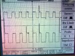
Currently when I connect an oscilloscope across the motor, I find that the voltage across the motor never reaches zero. When the PWM waveform is LOW, the motor keeps on moving and we get a reading of the back EMF on the oscilloscope.

Is there any way in which I could minimize the back EMF such that the waveform across the motor resembles a normal HIGH-LOW PWM signal?

I'm attaching an image for your reference. The top waveform is what I observe across the motor. Note how it never reaches zero (zero is marked by the arrow labeled '1' on the left) whereas the applied waveform is shown under it which reaches zero like it should (arrow labeled '2' marks zero for that wave).

P.S. I will also appreciate suggestions to eliminate those voltage spikes.
Pic.jpg
 

Why are you concerned that the voltage does not go to zero? It has no effect on the operation of the motor from the PWM signal.

The spikes can likely be reduced by a small capacitor (say 0.01uF) across the amplifier output.
 

This is part of a project I'm working on. I have a relay that connects the motor to a small secondary power source when the PWM is low. However the secondary power source is useless since the motor's back EMF is of a greater magnitude than the secondary source's.
 

Motor e.m.f. should be simply considered as a fact, of course varying with actual motor speed. If it your circuit can't handle it, think about a redesign.

For a detail discussion, you should show your PWM circuit. There are many variants, I don't want to jump into conclusions.
 

@FvM:

Thanks for the response.

I'm using this circuit for PWM generation:

An SPDT relay then monitors the High and Low of the PWM. If its High, the motor is connected to the PWM wave; if its low, the motor is connected to the secondary power source. I need to study the effect of the secondary source on the motor speed in conjunction with the PWM. However since the back EMF is greater than the secondary source's voltage, it's as if the source isn't even there.

I'm attaching the image for the relay circuit.

PWM Circuit - Multisim - [PWM Circuit ]_2012-09-02_17-15-06.png
 

Firstly, I have difficulties to see a real circuit behind the schematic:
What's the OP buffering the PWM output, is it a power OP, can it drive a motor or at least a relays coil?
You're driving the relays coil with the PWM wave, is it expected to switch at PWM speed? Is it a mechanical relays?

Secondly I'm unable to read a sense into the 0.5 V voltage source thing.

To start with a basic motor PWM topology, I would choose either a half bridge (unipolar, two quadrant motor operation) or H-bridge (bipolar, four quadrant operation).
 

I apologize for not providing specifics. Yes, it's a power opamp: OPA549. And yes, the relay is a mechanical one and it is switching; it is fast enough to switch with the PWM (switching time of the relay is 5 ms whereas the period of the PWM is greater than 700 ms with a transitioning time of less than 1 ms).

I will not be employing an H or half bridge for the circuit. My aim is to power the motor through another source when the PWM is low but I cannot do this since the other source's voltage is lower than the back EMF of the moving motor.

Should I just accept it how it is or is there a way for me to eliminate / minimize the back EMF?
 

Is there any way in which I could minimize the back EMF such that the waveform across the motor resembles a normal HIGH-LOW PWM signal?

Are you sure, back EMF is keeping the pwm voltage above zero?
 

There are types of motors that generate electricity when spinning.

Since your motor is sending out a voltage between power pulses, I believe it would try to charge whatever lesser voltage you hook up to it.
 

My aim is to power the motor through another source when the PWM is low....
If you want the motor to be powered even when the PWM output is low, then why connect it to the PWM in the first place? What's the point of a PWM with a 700ms period anyway?
 

700 ms sounds rather like motor start-stop control than what we usually know as PWM. I guess, noone noticed the 250 ms/div timebase in the waveform before.

There are in fact two kinds of EMF present in the circuit:
- the generatoric EMF that lasts while a DC motor is rotating
- the armature inductance "kickback" that can be seen as spikes in the waveform

The inductive kickback will definitely wear the relays contacts. IMHO it's questionable if a mechanical relays will stay this operation mode for long, but you can absorb the spikes by zener diodes or free wheeling diodes from the COM contact to the highest and lowest (ground?) power supply level.

An all-semiconductor motor control would be strongly suggested.
 

Status
Not open for further replies.

Similar threads

Part and Inventory Search

Welcome to EDABoard.com

Sponsor

Back
Top