Continue to Site

Welcome to EDAboard.com

Welcome to our site! EDAboard.com is an international Electronics Discussion Forum focused on EDA software, circuits, schematics, books, theory, papers, asic, pld, 8051, DSP, Network, RF, Analog Design, PCB, Service Manuals... and a whole lot more! To participate you need to register. Registration is free. Click here to register now.

MikroC Project check plz

Status
Not open for further replies.

janosandi

Full Member level 4
Joined
Jan 23, 2010
Messages
210
Helped
2
Reputation
4
Reaction score
2
Trophy points
1,298
Activity points
2,788
hello Guys
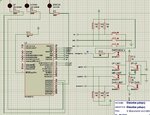
i've made a simple controlller for 3 stages elevator
the main problem is tht when testing on proteus it works great & even on real board its ok but sometimes it make errors.
Errors like not responding to emergency push button(which its normally cloesed) OR
converting the input pins to outputs & not respond to limit switch & it was a disaster
i've thought of ading wdt to my project & make the emergency switch cut off the main power of the pic
im using pic 16f877 with 4 mhz crystal which it drives 2 relays to drive 2 24v contactos
with 3 position select push buttons & position limit switches with 2 error switchs in case the main limit switch has failed
in proteus it works great
would you check my code & give me any advice

Thx guys
John
Code:
bit cnt;

void drvup(){
     if(PORTB.B4 == 0 && PORTB.B3 == 1 && PORTC.B0 == 1 && PORTC.B1 == 1) {  //emergency = false & up limit = false & error switches are off
     Cnt = 1;
     do   {
          PORTD = 1;   //drive up relay
     }
     while(PORTB.B3 == 1 && PORTB.B4 == 0 && PORTC.B0 == 1 && PORTC.B1 == 1&& Cnt ==1);
}
}
void drvmid(){
     if(PORTB.B4 == 0 && PORTB.B3 == 0 && PORTC.B0 == 1 && PORTC.B1 == 1 ) {  //emergency = false & up limit = false
     Cnt = 1;
         do {
            PORTD = 2; //drive down relay
            }
         while(PORTB.B1 == 1 && PORTB.B2 == 1  && Cnt ==1 && PORTC.B0 == 1 && PORTC.B1 == 1 && PORTB.B4 == 0);
}
     if(PORTB.B4 == 0 && PORTB.B1 == 0 && PORTC.B0 == 1 && PORTC.B1 == 1) {  //emergency = false & up limit = false
    Cnt = 1;
         do {
            PORTD = 1; //Drive up relay
            }
         while(PORTB.B3 == 1 && PORTB.B2 == 1  && Cnt ==1 && PORTC.B0 == 1 && PORTC.B1 == 1 && PORTB.B4 == 0);
}
}

void drvdwn(){
     if(PORTB.B4 == 0 && PORTB.B1 == 1 && PORTC.B0 == 1 && PORTC.B1 == 1) {  //emergency = false & up limit = false
     Cnt = 1;
     do {
     PORTD = 2;   // Drive down relay
     }
     while(PORTB.B1 == 1 && PORTB.B4 == 0 && PORTC.B0 == 1 && PORTC.B1 == 1&& Cnt ==1);
}
}
void drvdwn1(){
     PORTD = 2;    // drive down relay
     delay_ms(50);
     }
     
void drvup1(){
     PORTD = 1;   // drive up relay
     delay_ms(50);
     }
     
void emer(){
     if(PORTD == 2){
        PORTB.B1 = 0;
     }
}
void error(){
     PORTD = 4;
     Cnt = 0;
     }
void errorup(){
     if(PORTB.B5 == 0) { // Down push button
     drvdwn1();
     }
     PORTD = 4; // error lamp
     Cnt = 0;
     }

void errordwn(){
     if(PORTB.B7 == 0) {
     drvup1();
     }
     PORTD = 4;
     Cnt = 0;
     }

void InitTimer1() {
    //T1CON = 0x01;
    T1CON = 0x01;
    TMR1IF_bit = 0;
    TMR1H = 0xF8;
    TMR1L = 0x30;
    TMR1IE_bit = 1;
    INTCON = 0xC0;
}

void Interrupt(){
      if(TMR1IF_bit) {
      TMR1H = 0xF8;
      TMR1L = 0x30;
      PORTD = 0x00;
}
      TMR1IF_bit = 0;

      if(PORTB.B7 == 0) {    //up push button
      drvup();
      }
      if(PORTB.B6 == 0) {    // mid push button
      drvmid();
      }
      if(PORTB.B5 == 0) {    // down push button
      drvdwn();
      }
      if(PORTB.B4 == 0) {    //emergency push button
      emer();
      }
      if(PORTC.B0 == 0) {    // up error limit switch
      errorup();
      }
      if(PORTC.B1 == 0) {    // down error limit switch
      errordwn();
      }
      if(PORTB.B1 ==0 && PORTB.B3 ==0){   //if down limit & up limit switches are pressed together
      error();
      }
      if(PORTB.B1 ==0 && PORTB.B2 ==0){   //if down limit & mid limit switches are pressed together
      error();
      }
      if(PORTB.B2 ==0 && PORTB.B3 ==0){   //if mid limit & up limit switches are pressed together
      error();
      }
}

void main() {
    CMCON = 0x07;
    ADCON1 = 0x87;

    TRISA = 0x00;
    TRISB = 0xFF;
    TRISC = 0x03;
    TRISD = 0x00;
    TRISE = 0x00;

    PORTA = 0x00;
    PORTB = 0x00;
    PORTC = 0x00;
    PORTD = 0x00;
    PORTE = 0x00;

    InitTimer1();


}
elevator.JPG
 

Errors like not responding to emergency push button(which its normally cloesed)

I can't see an infinite loop "while(1)" anywhere. Anyway, except for some issue in hardware, I guess that the excessive use of delays in sequence could mask the read of inputs.
 
i dont think there is a need for infinite loop & about the delay i've used it works only in 2 conditions so its not important i think
 

There is nothing in your code seemingly spending much time to process such as standard libraries, math calculation, neither any closed loop instruction inspecting SFR registers. In addition, although the delay time of few dozens mili-seconds could induce the idea of a small interval, its proportion to the overall code in terms of processing time isn’t negligible. Keep in mind that your code will do nothing ( read input, change output ) in the meantime delay is running. I strongly recommend you reduce or eliminate delay just to make a test to confirm or refuse such an hypotesis based on the real-world circuit.
 
Do you have 100nF capacitors and some bigger electrolytic ones at your MCU pins?
Do you protect your MCU from relays by using diodes?
 

Do you have 100nF capacitors and some bigger electrolytic ones at your MCU pins?
Do you protect your MCU from relays by using diodes?

yes sure i have 100nf capacitor & diodes on relays
 

i've changed to 16F628 there is enough pins for my project
one qustion
is MCLRE enough to reset the MCU or should i use the emergency switch to cut the power off ?

thx for replys
 

RESET and POWER CUT will switch the output pins to z-state. If you will take a look on schematics of real devices, all outputs always being protected with h/w logic like 74xxx (AND, NOR).
 
There is nothing in your code seemingly spending much time to process such as standard libraries, math calculation, neither any closed loop instruction inspecting SFR registers. In addition, although the delay time of few dozens mili-seconds could induce the idea of a small interval, its proportion to the overall code in terms of processing time isn’t negligible. Keep in mind that your code will do nothing ( read input, change output ) in the meantime delay is running. I strongly recommend you reduce or eliminate delay just to make a test to confirm or refuse such an hypotesis based on the real-world circuit.

my problems not occurs in delay times
i have only 2 (50ms) Delays which its used only in error condition
 

Ok, but what about your layout ?
Please, tell us that you're not doing that on breadboard.

i'll try to put the board far from the 24AC contactors & im drawing a new board

- - - Updated - - -

RESET and POWER CUT will switch the output pins to z-state. If you will take a look on schematics of real devices, all outputs always being protected with h/w logic like 74xxx (AND, NOR).

i've decided to cut off the power its better i think in case the MCU has damaged
 

The better way is to use watchdog timer. In some cases even external one. And during initialisation analize reset vector source. If it is power cut or watchdog reset - do some logging.
 
The better way is to use watchdog timer. In some cases even external one. And during initialisation analize reset vector source. If it is power cut or watchdog reset - do some logging.

ok thx i've used WDT with assembly before i'll try to use it with mikroC i think i should use assembly to clear WDT right?
But how can i resume the same operation after reset ?
 

You can't resume operation from same place. It is impossible with PIC and you are not making electronics for space. Your purpose is to block all movable parts in case of h/w or s/w malfunction. If your device is stucked, you only need to know how it happens. You don't need any other functionality because if it is stuck, that means that it is not working properly. If so, no reason to use it any more. Problem should be solved, not workaraunded.
 

You can't resume operation from same place. It is impossible with PIC and you are not making electronics for space. Your purpose is to block all movable parts in case of h/w or s/w malfunction. If your device is stucked, you only need to know how it happens. You don't need any other functionality because if it is stuck, that means that it is not working properly. If so, no reason to use it any more. Problem should be solved, not workaraunded.

this is the problem
i couldnt know what is the problem exactly
i'll try to put the board far away from the contactors
thx
 

Just an example of my recent code:
Code:
	// Init pressure sensor
	BMP180_Struct.delay_func = vTaskDelay;
	BMP180_Struct.ReadReg = I2C_ReadReg;
	BMP180_Struct.WriteReg = I2C_WriteReg;
	BMP180_Struct.Resolution = 3;
	BMP180_Struct.I2C_Adrs = 0xEE;
	Error.BMP180 = BMP180_Init(&BMP180_Struct);
	if (Error.BMP180 == I2C_ADD_NOT_EXIST)
		ErrorHandle(BMP180, "BMP180 does not answer!\r\n");
	else if (Error.BMP180)
		ErrorHandle(BMP180, "BMP180 unknown error!\r\n");
Even if I check the sensor, I always print out some debug messages. Later on the debug will be switched off to reduce code size.

i didnt understand anything of this!!
anyway my problem is ok when i changed the same code to PIC16F628 & put it in other Box far away from the contactors
but in general how to set the unused pins of the mcu ?
set it to inputs or outputs ?
& as i see you dont like pics (Toy oriented MCU) so what do u suggest me to use ?
 

All unused pins have to be:
1. Connected to ground and defined as inputs
2. Not connected and defined as outputs
It is general for all mcu. Not only toy-pics)))
 

Status
Not open for further replies.

Similar threads

Part and Inventory Search

Welcome to EDABoard.com

Sponsor

Back
Top