Ashwini Kundur
Junior Member level 1

- Joined
- Jul 31, 2013
- Messages
- 15
- Helped
- 0
- Reputation
- 0
- Reaction score
- 0
- Trophy points
- 1
- Activity points
- 99
Hello
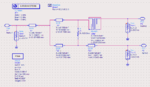
I am designing a microstrip balun and plan to do it by using a Wilkinson divider to divide the signal into 2 signals with equal amplitude and then a Lange coupler to obtain 90 degree phase shift between the signals. The problem is with this design I am getting S(2,1) and S(3,1) more than -3 dB. What can be done to rectify this and bring S(2,1) and S(3,1) within -3 dB limits?
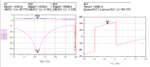
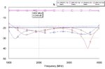
Here is a screen shot of S(2,1) that I am getting. Please help!

I am designing a microstrip balun and plan to do it by using a Wilkinson divider to divide the signal into 2 signals with equal amplitude and then a Lange coupler to obtain 90 degree phase shift between the signals. The problem is with this design I am getting S(2,1) and S(3,1) more than -3 dB. What can be done to rectify this and bring S(2,1) and S(3,1) within -3 dB limits?
Here is a screen shot of S(2,1) that I am getting. Please help!