nimeshasilva
Member level 1

- Joined
- Feb 9, 2010
- Messages
- 37
- Helped
- 1
- Reputation
- 2
- Reaction score
- 1
- Trophy points
- 1,288
- Location
- Sri Lanka
- Activity points
- 1,627
Hi all,
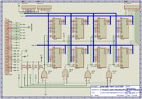
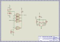
I'm recently working on a project of re-designing a memory card for a paper cutting machine (Polar Mohr EMC 92). It is a battery backed, removable card which consists of 8x TC5514 chips (2 chips x 4 groups to connect to 8 bit bus of the 8085, Please see the picture attached "1st and 2nd photos" the 2ns photo shows the WE buffering and battery connection). Because this machine is bit older, some memory chips have ended their lives,
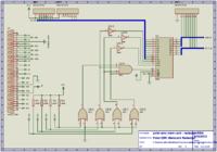
Since the Toshiba TC5514 (and other 2114 variants) are hard to find, thought of re-design the card with an Hitachi HM6264 chip. I've designed the circuit to interface with the HM6264 (Please see the attached 3rd photo) and the WE buffering and battery circuit will remain the same. thought of getting an expertise advice before implementing the solution. I have checked both data sheets and seems timings are compatible. So I think it is possible to do, However,
Please refer to attached photos and any kind advices, modifications, workarounds are welcome.
Thanks in advance.


