Continue to Site

Welcome to EDAboard.com

Welcome to our site! EDAboard.com is an international Electronics Discussion Forum focused on EDA software, circuits, schematics, books, theory, papers, asic, pld, 8051, DSP, Network, RF, Analog Design, PCB, Service Manuals... and a whole lot more! To participate you need to register. Registration is free. Click here to register now.

Megger specification explain.

Status
Not open for further replies.

xchcui

Member level 2
Joined
Mar 14, 2016
Messages
50
Helped
0
Reputation
0
Reaction score
2
Trophy points
8
Activity points
485
Hi.

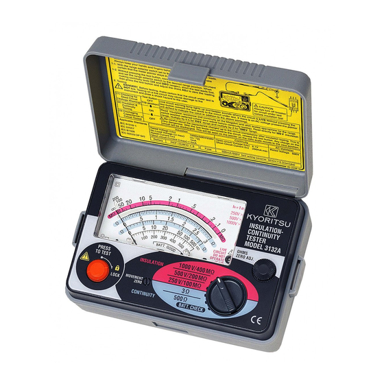
I have a cheap megger that can generate:250DCV/500DCV/1000DCV.
The manual of it says:if the measured resistance is less than 1.5MΩ
at 500DCV position or less than 5MΩ at 1000VDC position,the measurement
time mustn't proceed more than 10 seconds.
I assume that there is a kind of current limiting circuit inside the megger
that may heat-up and be damaged if the measurement will be more than 10 seconds at the above conditions.
But what does it mean less than 1.5MΩ(refer to 500VDC position)?
Less than 1.5MΩ is between 0Ω to 1.5MΩ(0Ω,140Ω,3KΩ etc...),so does it mean that i allowed to make the measurement for 10 seconds also when the resistance
are 1KΩ,200Ω or even 0Ω?After all,they are all less than 1.5MΩ resistance,
right?


megger 1.jpgmegger2.jpg
 

You have already written the answer. Max 10 seconds applies if the resistance is less than 1.5 MΩ at the 500V position. More than 1.5 MΩ => no time limit.
 

Power = heat is reciprocal of R so makes sense :

1666961437080.png

But at 500V, 1.5Meg, thats just .16W so......why the limit there ?


Regards, Dana.
 
Last edited:

I forgot to add an important spec.
On short circuit the current limiting circuit is limit the current to
about 2.5mA.
You have already written the answer. Max 10 seconds applies if the resistance is less than 1.5 MΩ at the 500V position. More than 1.5 MΩ => no time limit.
Yes,it sound like i can apply 10 seconds even when the resistance is 0Ω,
but i assume that the internal heat in the megger,when the resistance is 10Ω
,for example,will be greater than when the resistance is 1MΩ,isn't it?
So,i am trying to figure-out if the 10 seconds warning in the manual was based on
the worst case of a short-circuit(zero resistance).
Or in other words,can i make the measurement for 10 seconds when the resistance is 0Ω?
I am not expert with meggers,so i am not fully sure what is the meaning of this warning.
Power = heat is reciprocal of R so makes sense :

View attachment 179368
But at 500V, 1.5Meg, thats just .16W so......why the limit there ?


Regards, Dana.
And at 500V,10Ω it is 25000W;)
As i said,there is a current limiting to about 2.5mA,
so the wattage wont be more than:1.25W,i guess.
But my intention was to the situation of low resistance(like 10Ω)
and not to the 1.5MΩ value.
 
Any thoughts?
Does the warning mean that i can make the measurement for
10 seconds even at 10Ω resistance?
 

Can you post copy of manual.

Seems like if there is no qualifier in manual for the R value in the 10 sec limit
the answer is yes. But a precautionary measure would be to contact manufacturer
for guidance. Just a thought.


Regards, Dana.
 

    xchcui

    Points: 2
    Helpful Answer Positive Rating
Unfortunately,i couldn't make a contact with the
company who made this megger.
The megger is a non expensive made in china tool
and in the manual there is no(as you mentioned)
qualifier for the R value in the 10 sec limit.
Anyway,thanks for your help.
if i will smell something burning inside the megger,during the measurement,
i guess that then i will know for sure the answer:)
 
You could use an IR thermometer, do a 5 sec measurement, and read before./after
T of the TO220 transistor on it to see how much T rise you get.....


Regards, Dana.
 
  • Like
Reactions: xchcui

    xchcui

    Points: 2
    Helpful Answer Positive Rating
You could use an IR thermometer, do a 5 sec measurement, and read before./after
T of the TO220 transistor on it to see how much T rise you get.....


Regards, Dana.
And what parameters should i look for?how much T rise?
Is it the maximum temperature(100°C-150°C)of of the TO-220 transistor?
What temperature of the transistor,after 5 sec,should tell
me that the circuit is approaching its limits?
 
Last edited:

Resistance measurements are usually done by a current source and in this case the voltage generated is limited to 1kV, so the limit is always power and then thermal time constant and thermal resistance which raises the internal component temperature. usually to 125'C or less.

Pmax = V^2/R=1kV^2/5Meg = 0.2 Watt
A 1/4 W resistor will rise 100'C @ 25'C to 125 'C when loaded to 250 mW.

- so 0.2W has 25% margin ( derated from 250 to 200 mW
- temperature accelerates room temp failure rates which doubles every ~10'C rise due to Arrhenius law.

This is why you have these limits which are 1kV/ 5Meg = 200 uA which I suspect is the calibrated MEgger constant current (CC) source to measure leakage resistance in proportion to voltage.

If my assumption for max power rating was low, then the CC current will be higher.

This Megger uses 1 mA.
 
Last edited:
And what parameters should i look for?how much T rise?
Is it the maximum temperature(100°C-150°C)of of the TO-220 transistor?
What temperature of the transistor,after 5 sec,should tell
me that the circuit is approaching its limits?
Look up thermal resistance of that transistor and that way you can
calc die temp. Transistor also has a T junction max rating. that way
you can see how close you are to limits.


Regards, Dana.
 
  • Like
Reactions: xchcui

    xchcui

    Points: 2
    Helpful Answer Positive Rating
All datasheets will have ABSOLUTE MAXIMUM RATINGS with fine print. These should be treated as hard limits but show thermal resistance. This is a standard TO-92 and all devices are the same around 357 'C/W junction rise above ambient. The epoxy case is an electrical and thermal insulator TO-92 case that only gets about 1/3rd as hot as the semiconductor inside. You should target a design with environmental limits and power max. to not exceed 85'C with good reliability margins.

1667078143409.png


Resistors not having any fine features can tolerate a higher temperature, but then if enclosed may overheat and affect other parts. Here the carbon film 1/4 W through-hole resistor is more surface area and lower thermal resistance and higher operating limit. The incremental slope is the thermal resistance just like electrical resistance is the slope of R=V / I
1667078605317.png
 
  • Like
Reactions: xchcui

    xchcui

    Points: 2
    Helpful Answer Positive Rating
Reading the manual literally, you can assume it's safe to measure up to 10 sec for any DUT resistance between 0 and specified Rmin. This should be sufficient for everydays work, unless you want to reverse engineer the instrument.
 
If i understand right,i can assume that the 10 seconds warning is probably refer also to short circuit(0-Rmin).And i can verify that by checking the thermal resistance of the transistor by IR thermometer.
I guess that i can only measured the temperature of the case
and not the die inside.So the data:thermal-resistance of junction to case is
what i should use.
I assume that if i could attach an heatsink to the transistor i could make
the measurement more than 10 seconds,but i don't see how i can
do that,since there isn't enough room inside that small box.
Anyway my main question is solved so i'm good.:)
Thank you very much to everyone for your help.(y)
 

All datasheets will have ABSOLUTE MAXIMUM RATINGS with fine print. These should be treated as hard limits but show thermal resistance. This is a standard TO-92 and all devices are the same around 357 'C/W junction rise above ambient. The epoxy case is an electrical and thermal insulator TO-92 case that only gets about 1/3rd as hot as the semiconductor inside. You should target a design with environmental limits and power max. to not exceed 85'C with good reliability margins.

View attachment 179409
I read again the thread and i would like to clarify something.
You said that the epoxy case gets about 1/3rd as hot as the semiconductor inside.
So if in the datasheet it says that the max junction temperature is 150°C,
Does it mean that the epoxy case temperature must not exceed 50°C(1/3 of Tj)?
If yes,why did you mentioned the 85°C value that must not exceed?How did you
come to this value?
I meant to say 1/3 of the temp rise above 25'C. the 85'C refers to Tj from my calc. and measured MTBF experience.. also lower temp plastic will discolor nearby

that must also be factored by your internal ambient max.. my designs often derated Absolute max by 50% for thermals due to arrhennius effects on MTBF

momentary is tolerated but 10 sec. implies there is a time constant for temp rise and it is still ramping up.
 
Last edited:
The post TO-92 #12 considerations don't apply for TO-220 in free air. The package has much lower Rth-jc thermal resistance, respectively case temperature is near to junction temperature. For TO-92, the specified Rth values in datasheet suggest a case overtemperature of 2/3 rather than 1/3 times junction overtemperature.
 
Status
Not open for further replies.

Similar threads

Part and Inventory Search

Welcome to EDABoard.com

Sponsor

Back
Top