YoganathanS
Newbie
Hi Group members,
I am doing measurment in Lab for measuring the Efficiency of the standalone full bridge rectifier. I use RF amplifier for the input power for the rectifier and DC multimeter to measure the DC power at the outputs. My setup is working fine but with small problem, the input side of the rectifier consumes more power than expected and the probe from osscillscope is also creating grounding issue.
So, I am kindly asking if anyone can suggest me testbench in lab to measure the Rectifier efficiency.
Looking forward to hearing from you. Thanks in advance!
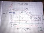
I have a attached my measurement setup.
I am doing measurment in Lab for measuring the Efficiency of the standalone full bridge rectifier. I use RF amplifier for the input power for the rectifier and DC multimeter to measure the DC power at the outputs. My setup is working fine but with small problem, the input side of the rectifier consumes more power than expected and the probe from osscillscope is also creating grounding issue.
So, I am kindly asking if anyone can suggest me testbench in lab to measure the Rectifier efficiency.
Looking forward to hearing from you. Thanks in advance!
I have a attached my measurement setup.