Continue to Site

Welcome to EDAboard.com

Welcome to our site! EDAboard.com is an international Electronics Discussion Forum focused on EDA software, circuits, schematics, books, theory, papers, asic, pld, 8051, DSP, Network, RF, Analog Design, PCB, Service Manuals... and a whole lot more! To participate you need to register. Registration is free. Click here to register now.

Measuring mains voltage

Status
Not open for further replies.

Jester

Full Member level 6
Joined
Aug 18, 2012
Messages
377
Helped
7
Reputation
14
Reaction score
7
Trophy points
1,298
Location
.
Activity points
4,754
I have been asked to design a circuit that will measure 3-phase voltage (0-120Vrms nominal), and then send the measured values via RS485 to another location.

There are two obvious approaches:
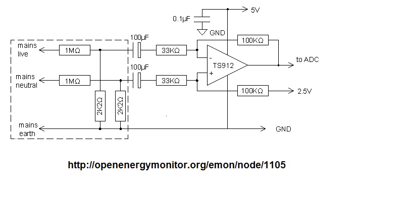
A) Use 3x step down transformer for isolation and then sample the secondary voltages with the A/D on a small uController.
B) Use 3x differential amplifiers to reduce the mains voltage to the A/D range of the uController and then use optical isolation for the RS485 signals.

Up and down sides to both approaches, down side as I see it:
A)
  • Weight, size and cost of transformers (must meet 60950 or 61010 safety criteria)
  • Accuracy of transformer
B)
  • IF line and neutral are reversed by customer through a wiring error, the "ground" of the uController becomes hazardous
  • Complexity of providing isolation for multiple signals (that will meet 60950 or equivalent criteria)

Thoughts and suggestions?
Any suggestions on low cost suitable transformers, if I choose route "A"?
 

I should have stated, that I need to sample the waveform 32 times per cycle and capture "spike" events, so ADC must measure individual points on waveform not an averaged or DC value.
 

Circuit on Figure1 shows a linear transfer of AC voltage to isolated output as AC voltage and not as DC equivalent. All normal spikes on AC mains will pass to output and can be measured with A/D in any manner you vant as shown on Figure2.
 
  • Like
Reactions: Jester

    Jester

    Points: 2
    Helpful Answer Positive Rating
Circuit on Figure1 shows a linear transfer of AC voltage to isolated output as AC voltage and not as DC equivalent. All normal spikes on AC mains will pass to output and can be measured with A/D in any manner you vant as shown on Figure2.

Thank you, looks like a viable option.

My gut feel is that a transformer approach is going to be less linear than isolating optically.

Will need to weigh the benefits of this analog optical approach compared to letting the uController live in the high voltage domain and then use low cost opto's to provide isolation for the RS-485 lines.

Comments welcome.
 

Do not be confused with ground symbol on Figure1. All what is on right side of optocoupler is galvanically isolated from mains. Only first OPA and left side of optocoupler together with transformerless supply are connected to mains.
RS485 line can be additionally isolated with optocouplers.
 

Do not be confused with ground symbol on Figure1. All what is on right side of optocoupler is galvanically isolated from mains. Only first OPA and left side of optocoupler together with transformerless supply are connected to mains.
RS485 line can be additionally isolated with optocouplers.

Thanks, yes I appreciate the grounds are isolated.

At this point I'm more inclined to have the uController (A/D) live in the MAINS domain and optically isolate the digital RS485 signals instead of the analog signals, benefits:
+ eliminates the non-linearity associated with the IL300
+ less expensive
+ less parts
- Care will have to be exercised when programming the uController to make sure Hot is Hot and Neutral is Neutral.
 

As you wish. IL300 itself is nonlinear but it has first photodiode connected as negative feedback in first OPA which linearizes transfer characteristic of optocoupler. LED diode current in optocoupler has such shape that Ip2 current has exact shape uf mains voltage. Nonlinear distortion is 0.08%. Last paragraph of the article describes overall parameters of this circuit:
The main specifications of the circuit are 5300V-ac-rms galvanic isolation, 0.08% linearity, 470-ppm/°C thermal shifts in VOUT, 2° phase shift at 50 Hz, and dc to 1-kHz bandwidth at –3 dB. If you connect the output to a 10-bit A/D converter, one LSB is equivalent to 0.5V in the 110V power line.

Yes it looks fairly good, however I will use a 12 bit A/D and hope to be closer to 0.1V resolution. Also wide temperature range so I would need to compensate for non linearity vs. temperature.

I found this low-cost circuit, it's not obvious to me why the capacitors are needed?
 

Attachments

  • MM1.bmp
    925.6 KB · Views: 71

1st you must be given an accuracy class.

I assume class that requires 0.2% max error under all conditions.

Dielectric strength : IEC 688 2.5KV AC rms 1 minute between input terminals & case.

This can be achieved with dual opto isolators to linearize one with the other using a MUX'd DAC output to result in zero difference for each polarity and phase. 0.1% resistor values are required.
 

hope to be closer to 0.1V resolution

In case this idea has not been suggested, consider making an expanded scale.

For instance, if voltage will never drop below 90 V, then set up your measuring system to respond only to volt levels from 90 to 120V.
 

1st you must be given an accuracy class.

I assume class that requires 0.2% max error under all conditions.

Dielectric strength : IEC 688 2.5KV AC rms 1 minute between input terminals & case.

This can be achieved with dual opto isolators to linearize one with the other using a MUX'd DAC output to result in zero difference for each polarity and phase. 0.1% resistor values are required.

This sounds more complicated (and expensive) than simply allowing the uController to live on the mains side and isolating two RS-485 lines that come out to the low voltage side. Yes no?

- - - Updated - - -

In case this idea has not been suggested, consider making an expanded scale.

For instance, if voltage will never drop below 90 V, then set up your measuring system to respond only to volt levels from 90 to 120V.

Need to measure down to 0V or close to it.
 

You're right. You can use the 3 phases to a Buck supply for micro in case of loss of any phase or better have battery backup.

Then use BiPhase code thru a 3kV signal transformer so there is no DC signal and it is self clocking.
 

You're right. You can use the 3 phases to a Buck supply for micro in case of loss of any phase or better have battery backup.

Then use BiPhase code thru a 3kV signal transformer so there is no DC signal and it is self clocking.

For the power supply I was thinking of something closer to this: **broken link removed**

Seems cheap and dirty.

- - - Updated - - -

Does anyone know what the capacitors accomplish in post # 9?
 

Yes we know. Capacitor has almost infinite impedance for DC and can have low reactance for AC. In your circuit they play exact that role.

What is SunnySkyguy suggesting is that in three phase system use supply from all three phase voltages instead of only one because if that phase fails you will be lost..
 
Last edited:

Does anyone know what the capacitors accomplish in post # 9?

Probably a safety factor, to provide galvanic isolation (sort of) from mains. I add 'sort of' because if they fail by shorting, you lose the safety factor.
They need to be rated to withstand peak mains voltage (and add another 50 percent for greater safety).

They are 100 uF. A large enough value, so that they pass the low frequencies of mains AC. In that sense it is still possible for your devices to be exposed to full mains voltage, if your project is not hooked up properly to mains wiring.

That makes sense, 100uF @ mains voltage is a really BIG cap. If the resistors stay intact voltage should be very low. I'm thinking of adding a pico fuse before 1M resistor. I could use a 47uF 25V ceramic (1206). The problem I see with the capacitor is that they won't be matched, and as a result will introduce some error (Xc=56Ω for 47uF).

Thoughts?

- - - Updated - - -

If the Earth connection is missing the entire circuit; opamp and uController would be flailing around at 60Vrms, the opto's on the digital lines would maintain safety, but not sure how well the measurement circuit would perform in this condition?
 
Last edited:

Does anyone know what the capacitors accomplish in post # 9?
AC coupling to shift the signal to the voltage range of the single supply amplifier. The 100 µF, resulting in high-pass cut-off frequency of 0.05 Hz has been apparently chosen for very low phase error, I wonder if it's really necessary. If so, you'll better go for a DC coupled amplifier.

A disadvantage of the differential voltage divider circuit in post #9 is that it needs high precision resistors if good common mode rejection is intended. It also involves a certain leakage current to ground, but it can be usually tolerated.

The temperature stability is several orders of magnitide better than isolation transformers or IL300 based circuits, only analog isolators with AD/DA converters respectively isolated AD frontends can compete with it.
 

Status
Not open for further replies.

Similar threads

Part and Inventory Search

Welcome to EDABoard.com

Sponsor

Back
Top