Continue to Site

Welcome to EDAboard.com

Welcome to our site! EDAboard.com is an international Electronics Discussion Forum focused on EDA software, circuits, schematics, books, theory, papers, asic, pld, 8051, DSP, Network, RF, Analog Design, PCB, Service Manuals... and a whole lot more! To participate you need to register. Registration is free. Click here to register now.

Measuring difference between current in live and neutral

Status
Not open for further replies.

cupoftea

Advanced Member level 5
Joined
Jun 13, 2021
Messages
2,611
Helped
54
Reputation
108
Reaction score
115
Trophy points
63
Activity points
13,685
Hi ,
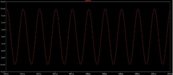
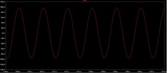
We wish to use this CT for detecting if the current in live and neutral is the same....and if different, how different?
Supposing there was 30mA of difference between live and neutral, then do you know what the output would be of this?

ZCT409 torroid Current transformer
 

You need to design the CT for the worst case imbalance you want to measure AND protection in case the phase is shorted to earth, lets say you get 600A pk in this case ( no return current ) the sec side has 6A rms - which thru 1k = 6kV ( this is why you never run a CT open ckt on the sec )
..Thanks, but i thought the CT would saturate long before this?

Also, suppose line and neutral wires are 3mm diameter, and the CT torroid aperture is 24mm diameter, then surely the coupling is going to be very poor and you wouldnt get 300uA out for 30mA in primary (1:100) ?

You need to know the core and winding parameters for a reasonable calculation.
Thanks, you mean the lineaerity of the flux density rise as current in primary increases?
..And how well spaced the windings are round the torroid perimeter?

I am seeing +/-10% accuracy in most offtheshelf CT's....thats if they quote it at all...presumably the ones that dont quote it are worse than 10%.

I dont think ive ever seen an RCD with current accuracy figures.

There is also the magnetising current...which as you know will be high if the secondary L is not high...since at 50Hz theres plentry of time for magnetising current to build up and cause big inaccuracy.?
 
Last edited:

Saturation is a volt.sec thing, so initially you will get the currents and voltages listed above.

For 50Hz, you would normally use a strip wound Si steel core, and then run it at very low flux, e.g 50mT max, this gives loads of headroom given that it can run to 1.5T, this also relates to the sentence just above.

Designing a CT is a reasonably complex thing, the 10% error you say you have seen - must be related to ferrite CT's that are run at too high a flux.
 
Thanks, it seems that an imbalance CT (two conductors going through it and measures the difference) would potentially be more accurate than a CT which simply reads the current in a single conductor passing through its aperture?...(you would expect this otherwise RCDs wouldnt be very accurate, and peoples health could thereby suffer)
Presumably , a CT torroid that has to measure from zero to 16Arms would presumbaly not be very accurate over that whole range?
 

Hi,

it´s just physics. (I don´t call it "accuracy")

Current runs in a loop. Thus the current to a load is exaclty the same but in opposite direction.
Every current creates a magnetic field. Now if two wires feed the identical current but in opposite directions, then the magnetic field compensates to zero. Exactly zero.

But when the current finds a "new path" (second path, shunt path) around the RCD, then resulting magnetic field is not zero anymore. If the magnetic filed is higher than the RCD threshold then it trips.

***
If you try to use two independent current measurements - each with it´s own accuracy error - and subtract the values to get the difference...it´s much more difficult.
On 16A when one error is +0.1% and the other is -0.1% then you get a difference of 32mA.

But when an RCD has an accuarcy error of 10% (mind: this is hundred times 0.1%) then it just causes to shift the trip current from 30mA to 33mA.

Klaus
 
Yes the differential RCD ( residual current device ) is far more accurate then trying to measure 30mA on 16Aac, or higher, hence it is the preferred engineering solution - a much smaller core can be used and a 30mA imbalance can be detected quite well. There is loads of information on how these work if you care to educate yourself. Also they are largely immune to fault currents ( except to earth - where models vary greatly as to how they handle this ).
 
Yes the differential RCD ( residual current device ) is far more accurate then trying to measure 30mA on 16Aac, or higher, hence it is the preferred engineering solution - a much smaller core can be used and a 30mA imbalance can be detected quite well. There is loads of information on how these work if you care to educate yourself.
Thanks, unfortunately, there is no information on what torroid to select so that you can make your own, highly accurate RCD. And Torroids_for_RCD use arent in digikey.
We need a highly accurate RCD......we want to be able to detect exactly what is the imbalance current......eg, we dont want to trip at 28mA imbalance, but do want to trip at 30mA imbalance...........for our use, at 50Hz, intuition kind of tells me that gretaer accuracy will be achieved by...
1....using an iron laminate torroid.
2....using as big as possible torroid
3......using a torroid with an aperture only just big enough to fit the live and neutral wires through it.
4.....Having as high as possible secondary coil inductance (i am taking live and neutral as effectively the "joint primary"), so that magnetising current error is as low as possible.

Woudl you agree?
 

basic physics and power electronics applies, there are loads of web pages advising on CT design, it is straight forward, at 50Hz, accuracy is more determined by the following electronics ....
 
there are loads of web pages advising on CT design, it is straight forward, at 50Hz, accuracy is more determined by the following electronics ....
....At the moment, we are using a ZCT409 imbalance torroid, to detect more than 30mA difference between live and neutral. (RCD trip function)
The ZCT409 gives just 9mV RMS output for a 30mA imbalance (as attached)....as you can imagine, its pretty horrendous to detect this amongst the noise.
There is no digikey section on imbalance torroids so that we can order one which allows us to get a better resolution than this.

ZCT409 imbalance transformer

Also the ZCT409 "datasheet" is open to interpretation......it says its rated to "225A"....does that mean that if the imbalance is 225A, then 500mA rms will flow out of the secondary?
Also, at what level of imbalance current will the torroid saturate?

Also, is there some reason that the "output resistor" has to be 130R as suggested in the datasheet?
--- Updated ---

Also, if you have the AL value for a torroid core, and the material composition of the core, then you can work out the saturation current for the core. Though torroid datasheets rarely if ever give an AL value, and rarely tell their material composition. The user is left guessing, and really is influenced to just by an offtheshelf RCD or CT.
The baisc rule of a CT, as you know, is to not saturate it, and to have the secondary inductance high enough such that the wanted signal current doesnt get distorted by the magnetising current. Also, to reset the core....but this isnt necessary of the primary current is bipolar.
Basically, torroid datasheets with sufficient data dont exist for the general user to carry out a design.
--- Updated ---

******_______*******______******______********______******_______*******_______
Hi,
Our contractor has selected the following imbalance CT for our 32Arms mains distribution box, its a ZCT409.Do you know why this was chosen?
The idea is to make an RCD, so it needs to detect an imbalance of 30mA between line and neutral.
This CT gives an imbalance current of 500mA rms if the imbalance is 225Arms (!!!)
So if the imbalance is just 30mA, then the output current is just 66uArms.
Do you know why such a CT was selected for this job? The ZCT409 doesnt saturate if the imbalance grows to 225A......which seems good....but when thinking about it.....the fuse/circuit breaker would blow if well under 225A flowed. So why do it like this? We also have a CT on the line conductor, so we could detect overcurrent like that, and have no need of the 225A rating of the ZCT409? What am i missing?
Surely we need an imbalance CT which allows a higher output current when imbalance is 30mA? Surely all we need is to select a CT which doesnt saturate as long as the imbalance is less than 32Arms?...make it 40Amrs for some margin?
Also, as attached, we are using a 130R burden resistor. So even if there was an imbalance of 225A, then the voltage across the burden resistor would grow to 65V, which would blow up the opamp that amplifies the burden resistor voltage (its supplied by +/-12V). Do you know why this has been done?
Please advise on What have i overlooked in my dim-wittedness concerning this?

ZCT409 datasheet:

*******----------*******---------*******----------*******---------*******----------*******---------
 

Attachments

  • Forum_imbalance transformer output.jpg
    Forum_imbalance transformer output.jpg
    93.7 KB · Views: 78
Last edited:

....At the moment, we are using a ZCT409 imbalance torroid, to detect more than 30mA difference between live and neutral. (RCD trip function)
The ZCT409 gives just 9mV RMS output for a 30mA imbalance (as attached)....as you can imagine, its pretty horrendous to detect this amongst the noise.
You need to have a resistor connected to the CT output and measure the voltage. Yes, you should have a amplifier to increase the voltage. Why you think it is horrendous?

Also the ZCT409 "datasheet" is open to interpretation......it says its rated to "225A"....does that mean that if the imbalance is 225A, then 500mA rms will flow out of the secondary?
The voltage will be reasonably proportional to the diff current; if 30mA deltaA gives 9mV, 1.6A deltaA will give you 500mV output.

I am not expert in chinese, but 225A must be related to the size of the conductor the hole can accommodate. Remember that you have to push two wires through the hole.

I do not know why the CT is having four wires. Two wires are necessary and sufficient.

Also, is there some reason that the "output resistor" has to be 130R as suggested in the datasheet?
Yes; the winding of the CT has some finite resistance. If you short the ends, there will be zero voltage. If you leave it open, you will get max voltage but lots of noise. This value is a compromise. You can use 100 Ohm or even 1K but not 100K or 1R.

Also, if you have the AL value for a torroid core, and the material composition of the core, then you can work out the saturation current for the core. Though torroid datasheets rarely if ever give an AL value, and rarely tell their material composition. The user is left guessing, and really is influenced to just by an off the shelf RCD or CT.
If you have a AC power supply and a scope and a blank core, you can get a decent idea about the saturation current of the core. If you google for it, you can perhaps find it yourself.
 
I am not expert in chinese, but 225A must be related to the size of the conductor the hole can accommodate. Remember that you have to push two wires through the hole.
Thanks, we have 2 conductors going through the hole, but they are only 4mm in diameter.....the torroid aperture is 24mm.....so do you think that our aperture is too big?
 

Thanks, we have 2 conductors going through the hole, but they are only 4mm in diameter.....the torroid aperture is 24mm.....so do you think that our aperture is too big?
It is desirable that the fit should be tight. But how much?

Magnetic lines of forces for a straight conductor are in concentric circles. Now some of them will miss the toroid for sure.

Now also consider that the toroid has some high permeability; let us say 100. That means, in layman's term, lines of forces will be 100 times more concentrated within the toroid. Say the core conductor is close to one side of the toroid; then these lines of forces will enter the toroid and stay within the toroid. There will be certainly some loose coupling but not too much I guess.

Conductor cross section 4mm dia can perhaps carry 100A or much more. The insulation will be another 2-3mm thick (total dia 4+6=10mm). You need to slide in two of them. Not too much space left after that.

The magnetic field from the two conductors cancel only if they are very close together. In this case they are close but separated by the thickness of the insulation, that is about 4-6mm. The cancellation is only approximate and good at large distance. You can test with a very small compass (use DC for this test).
 
ou need to have a resistor connected to the CT output and measure the voltage. Yes, you should have a amplifier to increase the voltage. Why you think it is horrendous?
Thanks....the attached is the output of the imbalance CT when the imbalance is 30mA and thus it should trip the supply....as you can see, this is a sine with 100uA peak........we would like a higher peak current output for 30mA of imbalance, so that we can reduce spurious tripping due to noise.
--- Updated ---

Conductor cross section 4mm dia can perhaps carry 100A or much more. The insulation will be another 2-3mm thick (total dia 4+6=10mm). You need to slide in two of them. Not too much space left after that.
Thanks, this is a great point......by the way, our conductors are very loose in the 24mm diam aperture.....the 4mm diam i speak of is the conductor and insulation......there is way too much room.
--- Updated ---

The magnetic field from the two conductors cancel only if they are very close together. In this case they are close but separated by the thickness of the insulation, that is about 4-6mm. The cancellation is only approximate and good at large distance. You can test with a very small compass (use DC for this test).
Thanks, another great point, really, since our conductors are way too small for the torrod aperture...we should really have them cable tied together so we get the field cancellation you kindly speak of?
 

Attachments

  • Forum_output current of imbalance CT with 30mA imbalance.jpg
    Forum_output current of imbalance CT with 30mA imbalance.jpg
    85.2 KB · Views: 71

Thanks....the attached is the output of the imbalance CT when the imbalance is 30mA and thus it should trip the supply....as you can see, this is a sine with 100uA peak........we would like a higher peak current output for 30mA of imbalance, so that we can reduce spurious tripping due to noise.
I have seen many noisy signals and this is not one of them!

So if you use a 1K load resistor, you will get 100 mV. With a 100 Ohm resistor, you will get 10 mV. They should also be clean - no visible noise.

With a 100 Ohm load, you will not see much noise any way (when the signal is 10mV).

You need to amplify (or use a 1k load) at least 10x, rectify and feed a solenoid. That is all.
--- Updated ---

The power available is too little to drive a solenoid directly. You can drive a relay (or a solenoid) with a transistor and then perhaps 100uA current can be used to trip it. To avoid noise tripping, you need to have a low pass filter.
 
Last edited:
I have seen many noisy signals and this is not one of them!
...thanks, though that wasnt demonstrating the noise...that was just a picture of the idealised waveform coming out of the secondary of the imbalance transformer (got from fiddling with LTspice)...showing how low current it is........if it was higher current corresponding to the 30mA of imbalance current, then would it not be easier to detect it without spurious noise tripping?

We must trip on 30mA of imbalance current and not spuriously trip on less than 30mA of imbalance current.
 

Hi,
There is no digikey section on imbalance torroids
I still think you misunderstand the "imbalance CT thing".
Every CT can be used to measure single wire current.
Every CT can measure difference current, if you put two wires through the CT.

So you don't need to look for a special "imbalance CT".
Just look for a CT that is rated above 30mA.

Klaus
 
If there is no internal burden R, and you fit your own, if it is too large the Vout will be too large and the V.sec seen by the core will take it too far up and down the BH loop - leading to inaccuracies - this is why they quote the Vout, to keep it accurate - you must amplify the ( presumably ) AC signal with an op-amp or similar - if you need to.
 
Hi, Is the aforementioned ZCT409 CT actually a fluxgate sensor?


One of the wire pairs is about 140mH so is obviosuly the secondary, but the other is some 330uH...so could be a "field coil" as used in some types of fluxgate transducer?
 

Thanks, but supposing it was a fluxgate field coil for feedback loop purposes.....then would it need a bipolar voltage input so it could flux the core in either direction?
Also, on the topic of "any AC CT being usable as a fluxgate sensor".......does a fluxgate core need a wide or narrow BH loop..?....also ditto Qu for an AC CT?

Can literally any AC CT be used as a fluxgate sensor?...(given the addition of whatever external circuitry)
...and if not, please why not?

If a CT torroid for 30mA AC/6mA DC detection has only one coil, then can it not possibly be used as in "fluxgate style"?
 
Last edited:

Also, is it possible to buy a type B RCD for EVSE that doesnt contain the contactor?...but just gives a signal for you to use to actuate a relay?
 

Status
Not open for further replies.

Similar threads

Part and Inventory Search

Welcome to EDABoard.com

Sponsor

Back
Top