Continue to Site

Welcome to EDAboard.com

Welcome to our site! EDAboard.com is an international Electronics Discussion Forum focused on EDA software, circuits, schematics, books, theory, papers, asic, pld, 8051, DSP, Network, RF, Analog Design, PCB, Service Manuals... and a whole lot more! To participate you need to register. Registration is free. Click here to register now.

Measurement of Leakage reactance using resonant??

Status
Not open for further replies.

micktosin

Junior Member level 2
Joined
Oct 13, 2011
Messages
24
Helped
0
Reputation
0
Reaction score
0
Trophy points
1,281
Activity points
1,509
Please how can I measure a leakage reactance of a llc half bridge transformer using resonance? Assuming the magnetizing inductance is 100uH, leakage= 20uH and capacitor = 1.4uF, turns ratio 9:3
 
Last edited:

You'll do this as a combination of open and shorted winding measurements.

As a first step, sketch a transformer equivalent circuit to clarify your definition of Lm, Ls and transformer ratio. Different models are used in literature, the difference matters particularly for large Ls related to Lm.

If you have the circuit, you should be able to calculate easily which inductance values will be seen at the primary respectively secondary terminals with the other winding open or shorted.

You select capacitors for a resonance frequency around the intended operation frequency, connect the transformer in a (preferably series) resonance circuit to a generator and tune for resonance (maxim voltage across L and C). Repeat for all inductance values you want to measure.

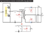
Hi FVM, Please find the attached document(I do hope it's displayed on the comment)

The Lm(magnetising) is the parallel inductor, while the Ls(leakage) or Lr (as shown on the diagram), is the series inductor. The switching frequency is 30Khz, the primary is 9 turns while the secondary is 3turns, intended to convert a 600V to 200V and 400A.
I do know how to measure the leakage and magnetizing inductance, however, calculating the leakage reactance using a formula has been the challenge without having to use a measurement device.

powerfig3.jpg
 

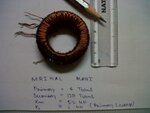
30uH leakage for 100uH magnetization is hell of a lot., especially for a transformer with such a low ratio. I have conducted a few laboratory tests on the following transformer, see attachment below
The magnetization is 52uH
Leakage = 0.8 to 1uH

However one of my professors said that the value of leakage calculated without actual loading can be misleading. He made a few students design a more powerful transformer than mine (2.5kW) and that turns out to have a lower internal impedance than what I calculated by resonance.

- - - Updated - - -

And of course since you are using a capacitor in the primary side, with an RMS current capability of over 150A! Can you explain which type of capacitor are you planning to use?!!
 

Attachments

  • IMG00058-20140508-1146.jpg
    IMG00058-20140508-1146.jpg
    456.6 KB · Views: 90

I do know how to measure the leakage and magnetizing inductance, however, calculating the leakage reactance using a formula has been the challenge without having to use a measurement device.

What is your definition of leakage reactance? Ordinarily, leakage reactance would be due to the leakage inductance. If you know your leakage inductance, and you know the operating frequency, calculating the leakage reactance would seem to be straightforward, wouldn't it?
 

The whole thread is about... how on earth to find the leakage inductance. And not about finding the reactance if the inductance is known.
 

The whole thread is about... how on earth to find the leakage inductance. And not about finding the reactance if the inductance is known.

The OP said "I do know how to measure the leakage and magnetizing inductance.", so apparently the thread is NOT about finding the leakage inductance.

It is about this request of the OP: "Please how can I measure a leakage reactance of a llc half bridge transformer using resonance?"

The OP is making a distinction between leakage inductance and leakage reactance.
 

Thanks, just understood leakage reactance and the relationship with leakage inductance. For deeper understanding how can I calculate the leakage inductance using theoretical value and not LCR meter? Most places I have been reading says you need empirical solutions to solve for Leakage inductance, as it is quite challenging? Any text book recommendation?

p.s Apologies for the stupid question as Physics is my background, so I am just beginning this journey into power electronics.

For clarification sake, I do know how to measure leakage inductance using LCR meter and not theoretical values.
 

In a rough estimation, leakage inductance depends only on the winding geometry rather than the core. (Not talking about core stray-field transformers with artificial magnetical shunt). In so far it can be estimated by analysis of an air coil transformer, usually as an axisymmetrical problem.
 
By the way 30uH leakage for a 100uH magnetization as far too large a value. It should be limited to, say, no more than 5uH. And in case of a good desing, 1uH to 2uH
 

By the way 30uH leakage for a 100uH magnetization as far too large a value. It should be limited to, say, no more than 5uH. And in case of a good desing, 1uH to 2uH
You didn't notice that the OP intends to make a LLC resonant converter which either works with artificial leakage inductance or an additional series inductor.
 
Status
Not open for further replies.

Similar threads

Part and Inventory Search

Welcome to EDABoard.com

Sponsor

Back
Top