Continue to Site

Welcome to EDAboard.com

Welcome to our site! EDAboard.com is an international Electronics Discussion Forum focused on EDA software, circuits, schematics, books, theory, papers, asic, pld, 8051, DSP, Network, RF, Analog Design, PCB, Service Manuals... and a whole lot more! To participate you need to register. Registration is free. Click here to register now.

Measurement of Leakage Inductance

Status
Not open for further replies.

sabu31

Advanced Member level 1
Joined
Jan 28, 2011
Messages
453
Helped
12
Reputation
24
Reaction score
13
Trophy points
1,298
Activity points
5,203
Hi all,

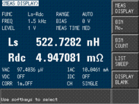
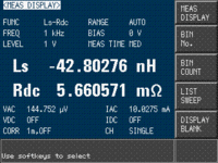
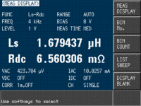
I want to measure the leakage inductance of a high voltage pulse transformer. The pulse width is 10us and frequency is 250Hz. The input voltage is to be at 500V and output at 4kV and 66A. I am using interleaved winding ( Secondary Half, Primary, Secondary Half). I am measuring leakage inductance using LCR meter by Keysight. However, at some frequencies I am getting negative inductance. what is the meaning of negative inductance shown in LCR meter. Also is this method of measuring leakage valid for low duty ratio pulse transformer.
 

Attachments

  • 3.gif
    3.gif
    9.5 KB · Views: 149
  • 2.gif
    2.gif
    9.4 KB · Views: 163
  • 1.gif
    1.gif
    9.5 KB · Views: 159

Thanks, Easy Peasy and SunnySkyguy for the reply. I have a query regarding among the available Toroidal, U Core, E Core which is suited for Lower leakage. I am getting both views that toroidal is good because of the closed magnetic path and E core is good because the number of more number of sides is enclosed in the core.

Also, I have seen that in Pulse Power Transformer by ETH Zurich, they are using winding in both the legs as compared to one leg of U core. Does that make difference if the core is wound on one leg instead of two if the number of layers are similar?


Leakage has NOTHING to do with the core shape chosen and everything to do with wdg layout - you can see this in the ETH paper ....
hint: the lowest possible leakage is obtained when the pri & sec occupy the same space .....
 
  • Like
Reactions: sabu31

    sabu31

    Points: 2
    Helpful Answer Positive Rating
The only thing I would add to improve is the copper Faraday shield tightly around the windings, if possible. I see the dual core as a double tuned BP filter with low Q.

" Since only the electric energy between the windings is considered, the distributed capacitance Cd is too small and results in a too small overshoot predicted by the transformer mode"


from (4)
\[ 2R_{load}*\sigma=\sqrt{\dfrac{L_L}{C}} \]
I use zeta instead of sigma and ESR of C and DCR of wire is ignored if << R load.

I thought it is the series 2Q = 1 / zeta for damping ratio, or \[ \zeta=\dfrac{1}{2Q} \] but then zeta is also used for skin effect.
 
Last edited:

    sabu31

    Points: 2
    Helpful Answer Positive Rating
If skin effect is affecting efficiency then choose Litz wire with the same turns . Or use flat magnet wire with mu foil & Cu foil loop shield around the ends to reduce the leakage. The breakdown voltage insulation and coupling C are tradeoffs but the best materials are >=50V/um if no impurities done in a clean room.

4kV is easy, try 40kV or 400 kV then you need to test with Partial Discharge measurements.

"
parasitics have
to be minimized in order to achieve the fastest possible rise time.
For example, to keep the rise time below Tr = 500 ns, Lσ ·Cd
has to be smaller than 4.75 ·10−14 if σ = 0 .75
"
 
Last edited:
Hi


for stray inductance the width of a copper bar (cross section) is not much of interest.
A 25x2mm bar will have about the same induactance as a 0.5mm diameter wire.

***
Also the length is no good measure for inductance.
Not quite. The inductance l:w ratio matters but only with a log relationship such that you should expect 0.8 nH/mm +/-50% depending on your choices. (If I recall from memory) This is why 2:1 MLCC caps (603, 805 etc) with very high SRF are 1:2 aspect ratio (l:w) from Murata to reduce inductance.
more important is the distance to the return path, or in other words: the enclosd area.
--> a 50cm twisted (signal with it´s return path) wire may have much less inductance than a 10 cm wire wide apart from it´s return path
Yes L increases with loop area.
**
Many power resistors a "wire wound". They act as a good inductor at higher frequencies. Thus they are not useful for HF measurements.

Klaus

Yes and No Cement filled cube power WW resistors are bi-filar wound to null the inductance (fold magnet wire in half and twist to make a resistor. But even so the leads outside the body are inductive 10~20nH and the coiled bi-filar wire must also be anti-coiled has tolerance errors.
1631907393319.png

Wound to maximize High Pulse Capability
So these can be used in the lower HF band.
 

Leakage has NOTHING to do with the core shape chosen and everything to do with wdg layout - you can see this in the ETH paper ....
hint: the lowest possible leakage is obtained when the pri & sec occupy the same space .....
Thanks Easy Peasy for the reply.
Does than mean for a Coil having Primary Turns as 4 and Secondary as 32 , should the secondary be split into 8 layers of 4 turns each with the primary turns being in between them.
Also I have come across literature where the coils are wound across both the limbs of U core with primary in parallel and secondary in series. Will this combination help.
 

The most effective winding method to reduce Cd is called Progressive.

It is an extension of the four section method ( with zig-zag windings) except twelve 30°sections are filled up, one at a time each with 1/12 the total number of turns. One may have to reduce the gauge by two wire sizes.

A barrier is frequently-used to separate the start and finish wires for further capacity reduction.
• Wrapping the unwoundcore with one or two layers of Mylar tape will reduce the capacitance even further. Teflon tape may be even more effective but usually is not required.
• Litz wire can significantly increase Q in the 50KHz to 2MHz range

Ref: p41 https://www.ieee.li/pdf/viewgraphs/fundamentals_magnetics_design.pdf


My opinion as follows;

To extend low frequency BW requires a low Ohms/Henry which reduces with a larger circular diameter by almost inverse square. L/R=T, 1/T=R/L=2.3 * f [Hz]-3dB for 1st order, assuming optimal fill factor for magnet wire.

[Ω/H] = k /OD^1.8 (OD in any units)
 
Last edited:

Status
Not open for further replies.

Part and Inventory Search

Welcome to EDABoard.com

Sponsor

Back
Top