Continue to Site

Welcome to EDAboard.com

Welcome to our site! EDAboard.com is an international Electronics Discussion Forum focused on EDA software, circuits, schematics, books, theory, papers, asic, pld, 8051, DSP, Network, RF, Analog Design, PCB, Service Manuals... and a whole lot more! To participate you need to register. Registration is free. Click here to register now.

MC34036 Boost Converter - falling whine tone / sound?

Status
Not open for further replies.

whitecollar

Junior Member level 1
Joined
May 15, 2010
Messages
16
Helped
0
Reputation
0
Reaction score
0
Trophy points
1,281
Activity points
1,446
Hi guys,

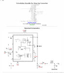
I have breadboarded a simple boost converter based on an MC34063 IC. I'm using an external NPN transistor to switch a higher current than the 1.5 Amps the IC can handle.

Input 12v DC
Output 25v DC to charge a 44,000 uF capacitor bank through a 39 Ohm resistor.

The circuit works fine, however there is a audible falling whine that happens about mid way through the charge time of the 44,000 uF capacitor bank and continues to fall until it's a steady low whine and the capacitor is fully charged.

I thought the MC34063 was a constant frequency device? Can someone please explain to me what's causing the frequency to fall and become audible as the capacitor bank charges? I need to have a silent circuit.

The schematic is attached.

Many thanks!

MC34036.jpg
 

check the switching freq and see if if it is in the audio band, your timing cap at 330uF is too large!, generally less than 1uF, the slow switching will cause high peak currents in the choke as the o/p volts climb and this is causing the audio noise, pretty hard on the transistor too! Regards, Orson Cart.
 

check the switching freq and see if if it is in the audio band, your timing cap at 330uF is too large!, generally less than 1uF, the slow switching will cause high peak currents in the choke as the o/p volts climb and this is causing the audio noise, pretty hard on the transistor too! Regards, Orson Cart.

That's a mistake on the schematic. Sorry. It's a 270 pF timing capacitor.

Andrew.
 

how is that inductor constructed? if you had used two sections of a core, the core or loosemenss of coil might cause the audible 'whine'.
ensure that the coil core fixed with some sealant. and the coil itself is tight and packed .
 

It's a 270 pF timing capacitor.
I had no doubt about it.

In fact, 34063 usually doesn't work at constant frequency due to it's on/off control method. Depending on the load situation, a number of cycles is left out, usually generating patterns and tones. There isn't much you can do about it with one of the worlds cheapest switch mode controllers.

I guess, the output transistor drive configuration can be improved however. The 1.2k base resistor seems to bring up a large off delay, this may contribute to the unwanted control behaviour. According to the darlington configuration, the drive current can be much lower, and the series resistor considerably larger than 180 ohm.

P.S.: I just noticed, that tpetar linked a 34063 circuit with a 0.04 ohm current sense resistor, resulting in about 7.5 A peak current for a 1.5 rated device. A bad joke?
 
Last edited:

how is that inductor constructed? if you had used two sections of a core, the core or loosemenss of coil might cause the audible 'whine'.
ensure that the coil core fixed with some sealant. and the coil itself is tight and packed .

It's a Panasonic inductor from Farnel so no problem there. Saturation current is 3.4 Amps. https://uk.farnell.com/jsp/search/productdetail.jsp?SKU=1749176

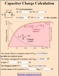
A 44,000 uF cap will draw a maximum current of 0.641 Amps at Time = 0 when charging (see attachment). capacitor charge 25v 39 Ohm.jpg

The MC34063 calculations show a peak inductor current of 2.8 Amps, which is well within the inductors margin for saturation (see attachment). MC34063 values.jpg
 

For such current loads bread board cant behave properly. better to assemble on a pre designed pcb or general purpose one with thick copper wires supporting high current paths.

please try reduce the Rsc from 0.1 to say 0.05 by placing another resistor in parallel.
 
Last edited:

please try reduce the Rsc from 0.1 to say 0.05 by placing another resistor in parallel.

Can I ask why? The calculations show that 0.104 Ohms is correct for my application, so I've used a 0.1 Ohm resister.

---------- Post added at 10:57 ---------- Previous post was at 10:53 ----------

I had no doubt about it.

I guess, the output transistor drive configuration can be improved however. The 1.2k base resistor seems to bring up a large off delay, this may contribute to the unwanted control behaviour. According to the darlington configuration, the drive current can be much lower, and the series resistor considerably larger than 180 ohm.

You may be onto something here. I tried replacing the base resister with a 180 Ohms one and the series resister with various values up to 1K. The tones reduce but they are still there, just. Also I noticed the IC gets a lot hotter now which seems strange, but this is because I've replaced the base resister with a lower value, right?

Can someone point me in the correct direction for these Darlington calculations because I'd rather do it properly and get the correct values. the MC34063 datasheet doesn't tell me anything about the series resister calculations etc, they just specify 180 Ohms.

Thank you very much!
 

0.3V / 0.1 ohm = 3 amps peak, thru the transistor, so need 300mA in the base (usually) + speed up impulse, compared to 58mA thru the 180 ohm, better to use a fet here I think. THere is a simple circuit that provides more Vpp ripple to the volt sense pin 5 and gives a more stable freq of operation over the load range, either that or a quieter choke.
 

0.3V / 0.1 ohm = 3 amps peak, thru the transistor, so need 300mA in the base (usually) + speed up impulse, compared to 58mA thru the 180 ohm
If you are referring to the circuit in post #1, the analysis is incorrect. The design implements a darlington circuit. So it rather suffers from too high drive current and particular large switch-off delay rather than too low base current.

I've used 34063 in product designs, it serves it purpose for moderate performance requirements. Using a recent switcher IC is clearly more fun.

P.S.: Referring to the darlington dimensioning. Because the current through the base resistor still contributes to output current, I would rather go for 10 or 22 ohm. Of course, it depends on the transistor data as well. Using a FET with a non-darlington driver, as suggested, can most likely improve the overall performance considerably. Gate-source resistor is still a critical parameter, because the deadtime of the hysteretic control loop directly affects stability.
 
Last edited:

Status
Not open for further replies.

Similar threads

Part and Inventory Search

Welcome to EDABoard.com

Sponsor

Back
Top