Continue to Site

Welcome to EDAboard.com

Welcome to our site! EDAboard.com is an international Electronics Discussion Forum focused on EDA software, circuits, schematics, books, theory, papers, asic, pld, 8051, DSP, Network, RF, Analog Design, PCB, Service Manuals... and a whole lot more! To participate you need to register. Registration is free. Click here to register now.

MAX414 non-inverting amplifer not working

Status
Not open for further replies.

mjxshipton

Newbie level 5
Newbie level 5
Joined
Sep 20, 2012
Messages
8
Helped
0
Reputation
0
Reaction score
0
Trophy points
1,281
Visit site
Activity points
1,374
I'm in a bind. I'm working on one of several major projects - a small radar system for my antennas class. Thing is, the hardest parts went easy, the ramp generator and active LPF. I'm on the last low-frequency part, a simple gain stage, and something is amiss.

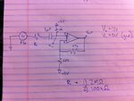
I've attached the schematic. They say to assemble the gain stage - thus 3 resistors, a cap and one op amp out of a MAX414 - and test it. It's in a non-inverting setup with a +5VDC bias. I've attached the relevant schematic.

I get nothing out of it. This has been plaguing me for about 5 hours. The LPF, which also uses the MAX414, works fine. But the gain stage gives me nothing.

I'm testing it with a 5Vpp + 5VDC offset sine wave, about 1-8kHz. I've measured both inverting and noninverting pins and output. On the output, I typically get "~1V." On the inverting pin, for a while I was getting ~4V, but now it seems to be giving me the positive cycle of the noninverting pin. Either way the output is still nothing. I even replaced the suggested capacitors with all 10ks to give me a simple gain of 2, but still nothing. At this point, I'm baffled. I have tried making the amplifier on the other pins, nothing, on anohter board, nothing. The active LPF still works fine.

I simulated the circuit in PSPICE, works completely fine. But real life isn't being so agreeable.

Would you happen to have any suggestions?

View attachment proj_schematic.pdf
 

It doesn't seem to have any errors although I can't find a data sheet for the LM2490 to check it's drop out voltage limit.

It appears you are using the +5V as ground so the supply is -5V and +7V, there is nothing wrong with that as long as the regulator holds up as the battery discharges. The only possible problem I can see is listed in the paragraph "Input Protection" on page 10 of the data sheet. Is it possible you are exceeding 0.1V differential input to the amplifier?

Brian.
 

Hey Brian,

Thanks for the prompt reply, I'm both elated and dismayed you're just as baffled.

As for the "Input protection," that depends if you could clarify: does this statement mean that the difference in voltages between the inverting and noninverting pins (9 and 10 in this case) cannot exceed +/- 0.1V? Or that each pin's bias voltage cannot exceed 0.1V? If you could clarify.

Again for reference, I used a 5Vpp+5Vdc input wave using just the "gain stage." I measured typically 1Vdc on the output (8) and about 4Vdc on the inverting pin (9). Sorry if I'm repeating myself uselessly, just trying to understand.
 

It's the difference between the + and - inputs that is limited, both can bear ground to supply as long as they do it together. The wording under "absolute maximum ratings" also states "Note 1: The amplifier inputs are connected by internal back-to-back clamp diodes. In order to minimize noise in the input stage, current limiting resistors are not used. If differential input voltages exceeding ±1.0V are applied, limit input current to 20mA." That contradicts the 0.1V mentioned on page 10 which I suspect is a typo, +/-1V is the more likely figure.

5Vpp input signal is far too high and will cause severe clipping on the waveform, the gain is adjustable to x46.5 so a signal level of no more than 0.2V peak to peak would be more appropriate. Possibly the clipping is causing a DC offset in your readings. Try removing the input signal, from regulator ground you should see around 5V on both input pins and the output pin. If the asymetric supply line is causing a problem, try adding a capacitor (try 10uF) in series with the 220 Ohm resistor. This will eliminate the DC current through it while not significantly affecting the AC gain at 15KHz.

Brian.
 

I'm thinking now it may be my FG. I'm using a laptop oscilloscope (Velleman PCSGU250) and according to the specs, the FG is 50ohm impedance, can't see an option to switch it to high impedance. Right now I'm just putting a big resistor (at least ~1Mohm) in series with the signal input (before the DC rejection capacitor), but I'm also going to take it to school and throw it on the "good" equipment. Could that be producing this?

I did what you said, removed the signal input, sure enough, 5V on all pins (~5.06 on noninverting input pin 10, ~5.16 on both inverting pin 9 and output 8). As soon as I turn on the FG, I get 1V on pin 8, regardless of waveform (0.2Vpp and 0.1Vpp 1kHz sine, DC offset = 0 or 5V (I tried both)). I've set it up with R = 10kohm for all (thus Gain ~ 2) as well as 47k for the resistor between 9 and 8 (thus gain ~ 6). Nothing, same old - if the FG is even connected, pin 8 (output) is ~1V, which is why I think that's the problem.

If that's true, then don't I have egg on my face, because I'm always reminding my students about that. What do you think?

EDIT: So I put a 2Mohm (1.88Mohm to be exact) resistor in series with the input capacitor (thus right after the function generator input going to pin 10). Adjusted the signal (had to turn it up to 10Vpp to register a readable signal on pin 10, which came up as about 68mVpp). However, it works - I got ~420mVpp output on pin 8, and given my current setup, with gain of ~6, this works out. To verify, I changed it to a 100kohm resistor and adjusted the FG amplitude (2.5Vpp) which gave me about 0.2Vpp on pin 8. Sure enough, I'm now getting 1.256V on the output. I tried it at both 1kHz and 5kHz, seems to work.

Could you elaborate on what's going on? What will happen when this is integrated with the rest of the circuit? Will it be fine or will there be problems?

Find attached both the schematic of the test setup I'm using along with a capture of the input and output when R=100k (and the FG is putting out 2.5Vpp + 5VDC). Again, if you could explain what's going on it'd be most appreciated, and thanks for all your help so far.

amplifier test.png

amplifier test setup.JPG

EDIT THE SECOND: I think I may know what the issue is, I'm going to try something and report back here. Key word: unity gain buffer.
 
Last edited:

I think it will probably work OK "in real life". There may be two problems and when removing the input leveled the voltages it tends to confirm it. Problem 1 is simply signal overload causing the output to stop being symetrical so it's average shifts in one direction. Problem 2 is that your input is already offset by 5V by virtue of the effective signal ground being the output of the 5V regulator. What you have in effect done is made the +5V rail the 'zero' rail with ground being -5V and the supply being +7V. When you apply the signal you inject from -5V to the input when really it should be from +5 to the input.

It would be worth experimenting by removing the regulator completely and using the connection between the batteries as ground with the other ends being -6V and +6V.

Brian.
 
Hey Brian,

I separately tested the device and setup in a lab with a dedicated power supply at +5 and +12V and a function generator (initial: 1kHz sine, 0.2Vpp, high impedance). With current setup (G~6), it worked perfectly, handling a signal up until around 1Vpp or so at which point as you said it hit the rails. The device clearly isn't autorecover as I had to power off all sources, but it worked fine again after too.

I considered that possibly, the signal is finding path to ground through the 100uF decoupling capacitor, which is connected from the 5V vreg pin to ground. With the 10k going from the input pin, this gives an RC constant of 1 second, effecting an AC short. So I used the last unused opamp in the MAX414 to make a unity gain buffer, with the 5V going directly from the vreg to the noninverting input (pin 12), pin 13 connected directly to 14, and my output from 14.

This has resulted in a slight change, now when the external power is off, I can see the input waveform (in my test case using again my laptop oscill a 500Hz 0.2Vpp sine), but once I flip the switch again all I see is ~1Vdc on the output, 4.5Vdc on the inverting pin, and 5VDC+ my sine wave on the input (pin 8). When I disconnect the function generator, again, all pins go to 5V, and this time all of them are at 5.16V (thus exactly the same).

Considering the input waveform is never negative - in fact never really less than 5Vdc, I figure I should be getting SOMETHING out.

Again I'm baffled. At least I know the chip and my setup work, just not when integrated with the rest of the circuit for some reason. At this point the 5V reference that the amplifier is using from the unity gain buffer is not connected to anything else other than the 5V going to the input pin, so it's effectively isolated.

Please advise if you can.
 

For absolutely no reason I can tell, it now works.

- - - Updated - - -

For absolutely no reason I can tell, it now works.
 

Status
Not open for further replies.

Part and Inventory Search

Welcome to EDABoard.com

Sponsor

Back
Top