Pedro147
Newbie level 5

- Joined
- Aug 3, 2012
- Messages
- 8
- Helped
- 0
- Reputation
- 0
- Reaction score
- 0
- Trophy points
- 1,281
- Location
- Australia
- Activity points
- 1,375
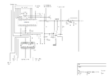
As a learning process I decided to try and manually control a 74HC595 shift register with switches. After cobbling a circuit together with my limited electronics knowledge and Google's help I got the attached circuit to work on a breadboard, I then decided to build it up on some veroboard and house it in a small metal enclosure. It was all working perfectly well but the last step was to fit a LM 7805 voltage regulator so I could power it from a 9 volt mains power adapter. Before I fitted the 7805 I was just using the 5 volts from an Arduino.
Prior to taking this last disasterous step whenever I first connected the power, I seem to remember that all the LEDS would be off. I would then switch the latch switch, grounding pin 12 of the 595 shift register, then enter the eight bits into the SR using a monostable pulse from a 555 timer into clock pin 11 of the 595, after selecting either a high or low data pin input via a switch to 596 data pin14 (grounded no LED on, + 5 V LED on) After the eight bits were in the SR I would open the latch switch and the selected pattern of LED's would display. Now whenever I first power the circuit up there are some LED's on, and if I quickly connect and disconnect the power, the LED's seem to be moving through the SR at each connect / disconnect action. This happens regardless of whether or not the latch switch is on or off.
As I said prior to trying to fit the power regulator, I thought that whenever I first connected the circuit all the LED's would be off. It all still works but you have to leave the SR unlatched with data pin 14 low and clear whatever LED's are on by inputing clock pulses until the SR is empty. Then you can clock in which LED's you want on. I do have an Atmega 328 in the circuit but it is only used to count through the eight clock pulses and display them on a 7 seg. With th help of pjdd on this forum, I did look at using a CD 4026 and a 74HC4017 but decided to use the Atmege 328 instead.
I have disconnected the 7805 and the two 10 mf caps to see if somehow whilst fitting them I had changed the circuit that was working but no luck. Also checked all ground connections and that the latch switch was grounding when in the latched position but no problems there.
I have attached the circuit schematics and was wondering if anyone might be able to suggest where I might look for the problem. I am assuming that I have understood the sequence of SR operation correctly, and that this explanation makes some sense.
Thank you Pedro.
Attachments
Last edited:

