Continue to Site

Welcome to EDAboard.com

Welcome to our site! EDAboard.com is an international Electronics Discussion Forum focused on EDA software, circuits, schematics, books, theory, papers, asic, pld, 8051, DSP, Network, RF, Analog Design, PCB, Service Manuals... and a whole lot more! To participate you need to register. Registration is free. Click here to register now.

Mains isolation with specialty transformer

Status
Not open for further replies.

Akanimo

Advanced Member level 3
Joined
Aug 30, 2016
Messages
866
Helped
146
Reputation
292
Reaction score
169
Trophy points
1,323
Activity points
7,280
Hi all,

I desire to measure mains voltage of 230Vac 50Hz as a means of protecting a pump from running at certain low voltages. I have been canvassing for a suitable way I can go about it in a way that I have galvanic isolation of the mains from my control system at a very low cost. I stumbled into this transformer by TDK Corporation:ATB322524-0110 and it is very cheap.
Below is the URL to its datasheet.
**broken link removed**

I intend to reduce the mains voltage by resistor voltage-divider network though.

Do you think this transformer suitable for the purpose? Do you think I should use some other isolation component instead?


--Akanimo.
 

The datasheet does not indicate the operating frequency, nor the maximum volt-second product.

But I suspect these are intended for a very specific high frequency circuit. My suspicion is corroborated by the very small primary inductance of only 7 uH. Normally a 50/60 Hz transformer will have a primary inductance 100 to 1000 times higher.

As such, they are not suitable for 50 Hz operation.
 
Hi,

the transformer is not suitable because:
* it is no 50/60Hz transformer. It is made for high frequency switching
* it is not made for safety isolation between mains voltage and low voltage.

Klaus
 

You need several 1000 V withstanding voltage and respective creepage and clearance distance for safe mains isolation. The part is absolutely unsuitable.

- - - Updated - - -

Consider a primary voltage measurement circuit and an optocoupler transmitting a digital "voltage good" signal.
 
...
Consider a primary voltage measurement circuit and an optocoupler transmitting a digital "voltage good" signal.

I thought of this before. The concern I have about it is that the whole of my comparator circuit is going to be on the mains side but take power from my controls side, across the isolation.
You think I could just tap the rectified-and-filtered mains to power the comparator? This tapped voltage will be varying in magnitude though but I can size it to be within range at all times. Is the idea okay?

Hi,

the transformer is not suitable because:
* it is no 50/60Hz transformer. It is made for high frequency switching
* it is not made for safety isolation between mains voltage and low voltage.

Klaus
Is there a better method I could use that is as low in cost or close?
 
Last edited:

Hi,

Maybe a stupid idea: Instead of measuring the live/mains, what about a parallel transformer for the control circuitry, like 230VAC:12VAC or something, that measures the unrectified AC but at a level to suit the comparator supply voltage, etc., with the rectification for the control circuit after the measurement point (measured at the transformer secondary output pins)? Over or under voltages would be proportionately reflected in the transformer secondary, wouldn't they?

All this assuming a relay of some kind is going to be used to cut off the brown-outs to the pump, then everything (except phase and neutral to the pump via a DPDT relay) could be on the secondary, isolated, side.
 

Hi,
...
Instead of measuring the live/mains, what about a parallel transformer for the control circuitry, like 230VAC:12VAC or something, that measures the unrectified AC but at a level to suit the comparator supply voltage, etc., with the rectification for the control circuit after the measurement point (measured at the transformer secondary output pins)? Over or under voltages would be proportionately reflected in the transformer secondary, wouldn't they?

All this assuming a relay of some kind is going to be used to cut off the brown-outs to the pump, then everything (except phase and neutral to the pump via a DPDT relay) could be on the secondary, isolated, side.

It is a solution I wish to have but transformer prices limit my choice. Should I get a transformer in bulk that is suitable and is lower than a dollar and fifty cents, I'd appreciate.
 

I built my house voltage monitors from cheap transformers. There are discount electronics mail order suppliers (eg., All-Electronics, Electronic Goldmine, Hosfelt was good but their website isn't running). I bought several transformers for a dollar or two. Or see if your local recycling center has used power supplies from discarded electronic gadgets.
 

]A possible approach with an opto isolator is to drive it with an appropriate sized resistor (or capacitor) from the mains.
(The negative half is clamped so the opto input is half-wave current waveform.)
This will generate a half-wave current at the output proportional to the input voltage, which can be converted to a voltage with a transimpedance connected op amp for good linearity.
This output voltage would be a good indication of the input voltage.
This half-wave signal can be filtered to give a dc voltage.

It would, however have to be calibrated, due to the variation in current-transfer ratio between opto units. (Measure the output voltage and compare it to the input voltage)
Is such a calibration acceptable for your application?
 
Last edited:

I thought of this before. The concern I have about it is that the whole of my comparator circuit is going to be on the mains side but take power from my controls side, across the isolation.
You think I could just tap the rectified-and-filtered mains to power the comparator? This tapped voltage will be varying in magnitude though but I can size it to be within range at all times. Is the idea okay?


Is there a better method I could use that is as low in cost or close?

This is an example of a 'self powered' isolated comparator I posted in another thread. The zener chain conducts and turns on the opto (shown active low on the secondary) when voltage exceeds the zener voltages. That current regulator shown could possibly be replaced with a resistor but makes the threshold more precise and limits wattage. It's just a peak detector and as shown only works in one polarity but may work for your application.

132984d1477167540-untitled.jpg
 
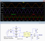
Here's the LTspice simulation of a circuit using a common 4N25 opto isolator, similar to what I mentioned in post #9.
I added a bridge at the input so the output is full-wave rectified instead of half-wave.
I used a resistor to generate the output voltage as I don't think a transimpedance amp has any significant advantage here, and it would have required a negative supply..
The output signal is filtered by R3C2 to give the average voltage of the rectified wave.
The simulation is shown for input voltages of 200Vac and 240Vac.


Capture.PNG
 

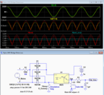
Here's the circuit with a pot replacing R1 to allow adjustment of the gain for calibration.
Note that R_Dummy is just to prevent a floating-node simulation error and would not be in the actual circuit.
(If it's not clear, Ix(U1:A) is the opto LED input current).


Capture1.PNG
 
These are very likely going to do the job.
Here's the circuit with a pot replacing R1 to allow adjustment of the gain for calibration.
Note that R_Dummy is just to prevent a floating-node simulation error and would not be in the actual circuit.
(If it's not clear, Ix(U1:A) is the opto LED input current).


View attachment 135744

Here's the LTspice simulation of a circuit using a common 4N25 opto isolator, similar to what I mentioned in post #9.
I added a bridge at the input so the output is full-wave rectified instead of half-wave.
I used a resistor to generate the output voltage as I don't think a transimpedance amp has any significant advantage here, and it would have required a negative supply..
The output signal is filtered by R3C2 to give the average voltage of the rectified wave.
The simulation is shown for input voltages of 200Vac and 240Vac.


View attachment 135727

Thanks guys for your contributions. They were all significant and I appreciate.

Some things I want to get cleared with optocouplers as used in this circuit (where the transistor is driven in non-saturation mode, unlike saturation mode where you supply enough current from the start to still be adequate continue to keep the transistor in saturation even when the CTR has degraded significantly) centers around CTR degradation.
What's the life expectancy of this circuit? Will it require diode current tuning or collector current tuning or both anytime soon?
How's the issue of CTR degradation tackled in this case?

Could someone please explain the concept and state the calculations behind this design for completion's sake? It will be very helpful in subsequent designs and I'd like to just be able to design one by myself when I need to.

Thanks and best regards.

--Akanimo.
 

Hi,

CTR degradation is a known issue with optocouplers.
(I made the experience with a self designed circuit where the CTR dropped to less than 30% of the datasheet specification within about 5 years)
For CTR critical designs there are special optocouplers with monitoring diode.
The datasheet usually provides circuits to compensate for CTR degradation.

Klaus

Thanks for your prompt response Klaus.
I'm just a bit bothered about my system having to inhibit the pump start at voltages that are much lower than designed, or even worse, stop working altogether in only a few years. It would more like defeat the purpose when that happens.
How are these special optocouplers identified? I might just go for a low-cost model of that class. Thanks.
 

I tend to think it may be easier to 'design out' the variations in CTR than calibrate for it. Though it depends on what your requirements are.

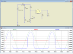
This circuit uses the TL431 for it's property as the cheapest reference/comparator that exists. The TL431 turns on when its ref pin exceeds 2.5V, as set by R3/R2. R1 should be set so there is roughly 1mA available at the turn-on threshold. More current is fine too it just burns up more watts. D2 is almost any zener between 5 and 30V.

I showed the secondary with 25V just so it would show up on the same scale as the AC in, obviously you can do what you need there.

This only has a single diode so it's 'half wave' but could have a full wave rectifier if you needed it to fire in both polarities. Though note that besides adding diodes that also effectively doubles the wattage of R1.

Capture.PNG
 
Hi,

I agree, that a "compartor style" solution on the mains side and a switching optocoupler may be a simple and robust solution.
The drawback is, that the threshold is not software-adjustable.

Klaus
 

I tend to think it may be easier to 'design out' the variations in CTR than calibrate for it. Though it depends on what your requirements are.

This circuit uses the TL431 for it's property as the cheapest reference/comparator that exists. The TL431 turns on when its ref pin exceeds 2.5V, as set by R3/R2. R1 should be set so there is roughly 1mA available at the turn-on threshold. More current is fine too it just burns up more watts. D2 is almost any zener between 5 and 30V.

I showed the secondary with 25V just so it would show up on the same scale as the AC in, obviously you can do what you need there.

This only has a single diode so it's 'half wave' but could have a full wave rectifier if you needed it to fire in both polarities. Though note that besides adding diodes that also effectively doubles the wattage of R1.

View attachment 135758

I can figure the concept in this design and it is cool. Could not figure it from Post #10. It makes even more sense that in your design the phototransistor is overdriven to saturation...and yeah, it takes care of CTR degradation. I'll give it a try too and see how it goes. I hope I can figure the concept for crutschow's design too (Post #13). Thanks asdf44, I appreciate.

- - - Updated - - -

Klaus, about the special optocouplers with monitoring diode, could you please tell how to identify them? Thanks.
 

Hi,


Look for "linear optocoupler" or "linear servo optocoupler"

One example is IL300.
Also read application note 50 from vishay.

Klaus
 
.........
Some things I want to get cleared with optocouplers as used in this circuit (where the transistor is driven in non-saturation mode, unlike saturation mode where you supply enough current from the start to still be adequate continue to keep the transistor in saturation even when the CTR has degraded significantly) centers around CTR degradation.
What's the life expectancy of this circuit? Will it require diode current tuning or collector current tuning or both anytime soon?
How's the issue of CTR degradation tackled in this case?

Could someone please explain the concept and state the calculations behind this design for completion's sake? It will be very helpful in subsequent designs and I'd like to just be able to design one by myself when I need to.
My circuit is analog and thus would need to be recalibrated if there is any CR degradation.
I'm not sure what the life expectancy would be.

My circuit simply uses a resistor to generate a rectified current in the LED proportional to the mains voltage.
This generates an output current in the transistor proportional to the input current, as determined by the CTR, which is converted back to a voltage by the resistor to ground.

In asdf44's circuit you could replace the zener with another Tl431, with a couple of resistors to set the desired "zener" voltage.
That would save buying another part type.
 
Last edited:
Status
Not open for further replies.

Part and Inventory Search

Welcome to EDABoard.com

Sponsor

Back
Top