Continue to Site

Welcome to EDAboard.com

Welcome to our site! EDAboard.com is an international Electronics Discussion Forum focused on EDA software, circuits, schematics, books, theory, papers, asic, pld, 8051, DSP, Network, RF, Analog Design, PCB, Service Manuals... and a whole lot more! To participate you need to register. Registration is free. Click here to register now.

Mains input harmonic current levels for rectifier/smoothing capacitor circuit?

Status
Not open for further replies.
T

treez

Guest
Newbie level 1
Hello,
We are examining the amplitudes of each of the Mains input harmonic currents to the following (shown below) Mains rectifier followed by a smoothing capacitor (235uF) and constant power load (50W).
Do you agree that the mains harmonic current amplitudes shown in the pdf below are correct? (The overall RMS current input from the mains is 611mA).

The simulation (in LTspice) is also provided, and this can be used with its “View FFT” function.

By the table of page 7 of the below document I believe that the circuit shown here is within the regulatory limits for mains harmonic current limits.

Harmonic current emissions:
 

Attachments

  • Mains Harmonic current levels.pdf
    8.9 KB · Views: 136
  • Mains Harmonic current levels.txt
    2.4 KB · Views: 94

You didn't tell about the equipment type, but if it's < 75 W rated power, EN 61000 doesn't apply despite of the poor power factor.
 
  • Like
Reactions: treez

    T

    Points: 2
    Helpful Answer Positive Rating
Thanks, though as you know, even if the power level is below 75W, its still possible to fail mains harmonic current limits if the post rectifier capacitance is too high. -Conversely, the smaller the smoothing capacitance, the longer is the rectifier diode conduction time, and the lesser in amplitude are the mains harmonic currents.
The equipment will be a guitar amplifier, of 320W maximum load power, -these are tested on 1/8 power for input current harmonics. -So that's 40W plus the bit extra for the SMPS inefficiency, ie, 50W in this case.
 

even if the power level is below 75W, its still possible to fail mains harmonic current limits if the post rectifier capacitance is too high.
I don't understand how this should be possible, as long as the standard says there are no limit values for instruments with real power consumption below 75 W. May be I missed a clause?
 
  • Like
Reactions: treez

    T

    Points: 2
    Helpful Answer Positive Rating
I think below 75w and you don't need to be PFC'd...but you still need to be under the limits for mains harmonic current levels..................I am sure you appreciate that if say, a 50W SMPS had say a 300mF capacitor after the diode bridge then the input current would be a train of very very narrow pulses, and this would fail the higher mains harmonics levels
 

but you still need to be under the limits for mains harmonic current levels
Which EN 61000-2-3 clause do you refer to?
 
  • Like
Reactions: treez

    T

    Points: 2
    Helpful Answer Positive Rating
Table 1 in page 7 of this...


..sorry I don't have the actual standard to hand
 

Please process the figure 1 flow chart. How do you manage to end up at class A (table 1) instead of "EN 61000-3-2 not applicable"?
 
  • Like
Reactions: treez

    T

    Points: 2
    Helpful Answer Positive Rating
This standard does not apply to (and has no limits for):

Non lighting equipment with rated power of 75W or less
 Arc welding equipment intended for professional use.
 Professional equipment (not intended for sale to the general public)
 Heating elements with symmetrical control methods and input power less than or equal to 200W.
 Independent dimmers for incandescent lamps with rated power less than or equal to 1kW.
 
  • Like
Reactions: treez

    T

    Points: 2
    Helpful Answer Positive Rating
Please process the figure 1 flow chart. How do you manage to end up at class A (table 1) instead of "EN 61000-3-2 not applicable"?

I don't think EN 61000-3-2 talks about Mains harmonic currents.....EN61000-3-2 is purely about power factor. Yes I agree that to have unity power factor you should not have mains harmonic currents, however, another standard applies the Mains harmonic current levels to literally all equipments, no matter what the power.

...just imagine if every sub 75W SMPS had say 100mF after the diode bridge.....the overall harmonics in the mains supply system would be terrible.....I know its unlikely to be 100mF in every SMPS, but you get the point.
 

Thanks , but I am sure that 61000-3-2 is the power factor one, the wiki article confesses that it may be "confusing" and offers readers to correct it.

I am sure we all agree that if every <75W offline SMPS on earth had 100mF after the rectifier, then the mains supply system would be full of unwanted harmonics....this is why we still have harmonic limits for <75w offline smps.
 

I am sure we all agree that if every <75W offline SMPS on earth had 100mF after the rectifier, then the mains supply system would be full of unwanted harmonics....this is why we still have harmonic limits for <75w offline smps.
It's O.K. to say I don't exploit the lax regulation for < 75 W devices. But if you just follow EN61000, there are no harmonic limits.

I don't think EN 61000-3-2 talks about Mains harmonic currents.....EN61000-3-2 is purely about power factor.
Did you even notice the title of EN61000-3-2? "Limits for harmonic current emissions (equipment input current <= 16A per phase)"
 
  • Like
Reactions: treez

    T

    Points: 2
    Helpful Answer Positive Rating
The thing is also that it will be harder to pass conducted emissions tests for <75W SMPS's if one uses an enormous dc bus capacitor such that the mains input current is just a train of short "spikes" of high current peaks with duration say less than 1 millisecond every 10ms.
 

The question is, can the rectifier circuit generate a relevant interference level above 150 kHz? I seriously doubt.
 
  • Like
Reactions: treez

    T

    Points: 2
    Helpful Answer Positive Rating
The book “Demystifying switching power supplies”, By Raymond Mack states that the harmonics of such a mains rectifier bridge followed by smoothing capacitor go well up into the MHz range.
 

Best to follow all regional standards and choose which you want to include.
e.g. Regulatory Product Certification Marks UL, ETL, CE, CSA, RoHS, Energy Star and DLC


Either THD <20% (includes all) or 3rd and 5th harmonic < -26dB if linear rolloff.

with P.F>90%

https://www.falstad.com/fourier/

IEC 62717 requires PF>0.9 above 25 W, as does CE-Mark Eco-Design
The present ES Luminaire spec requires PF>0.9 for commercial
California Title 24 for 2016 requires PF>0.9
DLC requires PF>0.9 and THD <20%
China CQC requires PF>0.9 above 15 W
Korea requires PF>0.9 above 5 W

- - - Updated - - -

Current limit pulse into ESR of caps + diodes + copper is a square edged pulse, so of course harmonics can extend to 5 decades of equal spectral density above fundamental and some will amplify with resonance.
No mystery.
 
  • Like
Reactions: treez

    T

    Points: 2
    Helpful Answer Positive Rating
Current limit pulse into ESR of caps + diodes + copper is a square edged pulse, so of course harmonics can extend to 5 decades of equal spectral density above fundamental and some will amplify with resonance.
No mystery.

...Thanks SunnySkyGuy, so you sound like you agree that the conducted emissions emc will be harder to pass, if an oversized post mains rectifier bridge capacitor is used? (as you know, conducted emissions test for offline smps is from 150KHz to 30 MHz)
 

The thing is also that it will be harder to pass conducted emissions tests for <75W SMPS's if one uses an enormous dc bus capacitor such that the mains input current is just a train of short "spikes" of high current peaks with duration say less than 1 millisecond every 10ms.

Easy thing to remember is ;

- a repetitive impulse has infinite spectrum of equal spectral density with spacing equal to rep rate.
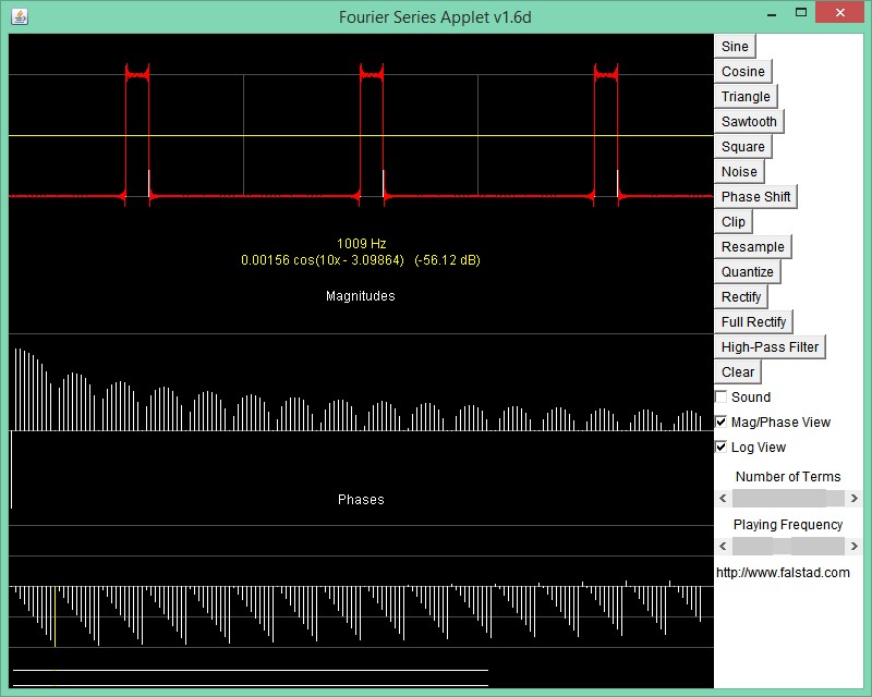
- a rectangular pulse of width t will have equal density to a null at the one cycle frequency and every recursive multiple with declining amplitude declining 1/n
- a triangular pulse is the same except rolling off at 1/n^2 ( since it is integral of pulse)

Here is 1ms pulse ever 100ms with only 159 harmonics shown

1190222000_1429984188.jpg


Also
Since a square wave is 50% the null is on the 2f and all even harmonics
If a 2f value exists it due to the % asymmetry and one can determine asym. directly from 2nd harmonic level. 0% error = - ∞, 0.01% error = -43 dB 0.1% -33dB etc ( from memory)
 
  • Like
Reactions: treez

    T

    Points: 2
    Helpful Answer Positive Rating
Status
Not open for further replies.

Part and Inventory Search

Welcome to EDABoard.com

Sponsor

Back
Top