Continue to Site

Welcome to EDAboard.com

Welcome to our site! EDAboard.com is an international Electronics Discussion Forum focused on EDA software, circuits, schematics, books, theory, papers, asic, pld, 8051, DSP, Network, RF, Analog Design, PCB, Service Manuals... and a whole lot more! To participate you need to register. Registration is free. Click here to register now.

Magnetic field formulation

Nils227

Junior Member level 2
Joined
Jul 27, 2023
Messages
20
Helped
0
Reputation
0
Reaction score
0
Trophy points
1
Activity points
207
Hello,

Assuming that we have a single-phase electrical transmission line (short distance (< 50 km), stranded, non-isolated, made of aluminum conductor steel reinforced), I would like to know the resulting magnetic field (shape, structure, absolute value, and all other possible details) when the line is being injected by different RMS values of an AC current of 50 Hz. It is intended to have a mathematical model formulation of the resulting magnetic field, so that it is possible to know the Tesla value of the magnetic field directly when the RMS value of the injected current is known.

In other terms, I am looking for the Biot-Savart formulation but for an AC current (instead of DC).

Any comments or possible related book chapters will be much appreciated

Thank you
 
try this
--- Updated ---

on second thought, your situation is not a moving current and not relativistic.

i'll go out on a limb here:
the whole point of using RMS for AC is that it amounts to DC for power purposes
as in the behavior of a resistor, using RMS values works

if you apply RMS valuse in the Biot-Savart Law, you'll get the magnetic field
then add back the sinusoidal part at the correct frequency

sorry, no references
 
Last edited:
try this
--- Updated ---

on second thought, your situation is not a moving current and not relativistic.

i'll go out on a limb here:
the whole point of using RMS for AC is that it amounts to DC for power purposes
as in the behavior of a resistor, using RMS values works

if you apply RMS valuse in the Biot-Savart Law, you'll get the magnetic field
then add back the sinusoidal part at the correct frequency

sorry, no references
Thank you dear wwfeldman for your valuable comment.

I honestly did not understand the sequential flowchart behind your ideas.
 
look at this

demonstration 8.2.1 says to use an AC current and (apparently) makes no changes to Biot-Savart
Thank you very much for this clarification.

Other than the "stick model" in the demonstration 8.2.1:
1. refers to a solenoid (and NOT a stranded wire)
2. calculates H on the internal axis of symmetry of the solenoid (and NOT with respect to an external point in space, at an axial location)

> The required solution shall be as follows: a mathematical function that has the current's intensity (in Amperes) and frequency (in Hertz), in addition to the cable's length and geometry (thickness, number of stranded wires, etc.) as inputs, then consequently outputs the magnetic flux density (in Tesla) at an arbitrary point in the space.

Suppose that the stranded wire lies (coincides) on the x-axis in a Cartesian plane; this wire begins at (0;0;0) and stretches forward the positive x-axis until its length: what would be the flux density at a point P (x;y;z) located in the same plane, that has the following coordinates:

x = 1 meter
y = z = 0.15 meter
 
There are many variants of such a model, depending on how accurate you want to be. For example, if your observation point is sufficiently far from the line, you need to include time-delay (retardation) effects. I would suggest starting with simple models from elementary electromagnetic texts, and working up from there.

To get the best (most accurate with least effort) result, I'd suggest simulation. Is there a reason you need an analytical solution?
Thank you PlanarMetamaterials

My observation is not to be sufficiently far from the line: only a maximum distance of 15 cm. I need the analytical solution (formula) as an "Input/Output blackbox", that according with the mentioned inputs (current value, frequency, line's length, etc,) it simply outputs the flux density in Tesla.
 
Is your line a single wire (SWER) or a traditional line, that means two wires ? In this last case you have to consider the interaction between the electric fileds generated by the two wires. The geometry here plays an important role.

I don't think the frequency (I mean low frequency on the order of 50-100Hz) can play a significant role, as well as skin and proximity effects. Also the time delay contribution could be considered negligible, especially for measurement near the wire. If you want very accurate estimation you should include all of them (and possibly the radiation resistance that in practice is negligible), but I think it could be a unecessary effort and the simulation could by the only practical way.

I will go simply applying the Biot-Savart law , taking into account the geometry of the line if necessary. Probably the results will have a lack of accuracy going close to the ends of the line.
Thank you albbg,

As initially stated, it is a single -stranded- non-isolated wire (like the one used in the overhead transmission lines).

So I go with the Biot-Savart law, in order to calculate B, despite that the current is of AC?
 
The Biot-Savaart law should give you a nice approximation. If you want a realistic setup, don't forget to to include all of the currents (i.e., the ones in the ground). Modelling the ground is of course its own difficult task.
 
Thank you albbg,

As initially stated, it is a single -stranded- non-isolated wire (like the one used in the overhead transmission lines).

So I go with the Biot-Savart law, in order to calculate B, despite that the current is of AC?
Ok, just to be sure to have correctly understood: you have a single stranded wire to distribute the main, then the return current will flow through the earth that is you have a Single-Wire-Earth-Return (SWER) system.
If you just want a value of the field, at the given location, you can put in Biot Savart the rms current (if you need the rms value) or the peak if you need this value.
Hi
Actually we are not concerned at this stage about the return current: we can imagine it as a delta-configured transmission system (3-phase), where we want to know the resulting magnetic field from the current flow through one of the 3 overhead wires.

Thank you for suggesting the Biot-Savart law for approximating the resultant magnetic field, but I need an alternative model that takes into consideration the geometry of the transmission line.
 
A three-phase delta-configured TL system will produce a significantly different magnetic field profile than a single phase in isolation (but of course, superposition can be applied). If you want to take into account the stranding of the cable, I would also recommend using superposition.

All in all, I think I would still suggest simulation as the optimal solution here. Modern field solvers such as HFSS let you adjust inputs in post-processing, i.e., you can adjust the currents and see the resulting magnetic field in real time without needing to re-run the simulation.
Thank you for your appreciated suggestion.
Any guidance for a first approach of HFSS usage regarding the intended solution?
 
Any guidance for a first approach of HFSS usage regarding the intended solution?
Ensure that you use a driven terminal solution.
I assume other (less expensive) softwares could achieve the same thing, but I'm not familiar with any others.
 
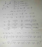
The simulation will give for sure the more accurate results. In any case you can try to calcualte the field using Biot Savart taking into account the geometry of the line. If the three wires are always separated one each other the calculation is not difficult. You can use the superposition applied to the three signals (not their RMS or peak value). I derivated the field for you. A, B and C are the three lines, P is the measurement point and dA, dB and dC are the respective distance between a line and the point P. These can be calculated by means of a simple geometry formulas.
Please check the correctness of my calculation before to use it.
 

Attachments

  • 20230802_164924.jpg
    20230802_164924.jpg
    120.4 KB · Views: 66
The simulation will give for sure the more accurate results. In any case you can try to calcualte the field using Biot Savart taking into account the geometry of the line. If the three wires are always separated one each other the calculation is not difficult. You can use the superposition applied to the three signals (not their RMS or peak value). I derivated the field for you. A, B and C are the three lines, P is the measurement point and dA, dB and dC are the respective distance between a line and the point P. These can be calculated by means of a simple geometry formulas.
Please check the correctness of my calculation before to use it.
Hi,
I thank you immensely for your drained efforts in realizing the posted reply!
Attached in the same manner is my reply, hoping to hear back from you
 

Attachments

  • Capture.PNG
    Capture.PNG
    2.2 MB · Views: 70
I'll try to answer your questions:

2. you are rigth, in a three phase system the currents Ia, Ib and Ic are shifted by 120deg each other (supposing a well balanced resistive load). I forgot a "2" term i.e. instead of pi/3 consider 2*pi/3 and instead of 2*pi/3 consider 4*pi/3

3. Simply consider that the phase change by 2*pi in the period T=1/f of the wave. This means that an interval Dt corresponds to a phase shift of 2*pi*Dt. You can write "2*pi : fi=1/f : Dt" and solve by the phase "fi". Furthermore remember that by definition, if the phase is "fi" than w = dfi/dt

4. the term "sin (wt+fi)" represents the time dependance of the field at the point "P". The term "dx" is the equivalent of "R" that is the distance of P from the line
The current is expressed as a time varying variable in which the line phase shift has been taken into account as well as the delay due to propagation from the line to the point "P" (even if at these frequencies is negligible, I just did a general derivation) at the velocity of the ligth
Separating the terms "sin(wt)" from "cos(wt)" you can apply the superposition adding all the factors of "sin(wt)" and "cos(wt)". Is the in-phase and quadrature decomposition

5. see above point 4.

6. Yes if you consider just a wire very distant from the others two of the line you must find again the Biot-Savart applied to a single wire: is correct. The "variable" that represents the geometry of the line is the formula the allows you to find the distances "da", "db" and "dc", given the coordinates of the point "P". You coud, for example, place the delta shaped line with the center of your coordinate system. Then knowing the distance between the wires (that usualy is fixed) is very simple calculate the relative distances with respect to a point "P" placed in the same cartesian plane.


I hope my answers are clear enough to you
 
Thank you for suggesting the Biot-Savart law for approximating the resultant magnetic field, but I need an alternative model that takes into consideration the geometry of the transmission line.
Biot-Savart is the exact solution for magnetic field calculation. Geometry will be considered by superimposing the field of conductor filaments. That's what a FEM tool does for the magnetostatic case. Current distribution is determined by resistance distribution, in the AC-magnetic case also field interaction (skin and proximity effect). For the field at a certain distance to conductor, these effects can be most likely ignored. Field of the other (return or other phase) conductors definitely matters.
 
I'll try to answer your questions:

2. you are rigth, in a three phase system the currents Ia, Ib and Ic are shifted by 120deg each other (supposing a well balanced resistive load). I forgot a "2" term i.e. instead of pi/3 consider 2*pi/3 and instead of 2*pi/3 consider 4*pi/3

3. Simply consider that the phase change by 2*pi in the period T=1/f of the wave. This means that an interval Dt corresponds to a phase shift of 2*pi*Dt. You can write "2*pi : fi=1/f : Dt" and solve by the phase "fi". Furthermore remember that by definition, if the phase is "fi" than w = dfi/dt

4. the term "sin (wt+fi)" represents the time dependance of the field at the point "P". The term "dx" is the equivalent of "R" that is the distance of P from the line
The current is expressed as a time varying variable in which the line phase shift has been taken into account as well as the delay due to propagation from the line to the point "P" (even if at these frequencies is negligible, I just did a general derivation) at the velocity of the ligth
Separating the terms "sin(wt)" from "cos(wt)" you can apply the superposition adding all the factors of "sin(wt)" and "cos(wt)". Is the in-phase and quadrature decomposition

5. see above point 4.

6. Yes if you consider just a wire very distant from the others two of the line you must find again the Biot-Savart applied to a single wire: is correct. The "variable" that represents the geometry of the line is the formula the allows you to find the distances "da", "db" and "dc", given the coordinates of the point "P". You coud, for example, place the delta shaped line with the center of your coordinate system. Then knowing the distance between the wires (that usualy is fixed) is very simple calculate the relative distances with respect to a point "P" placed in the same cartesian plane.


I hope my answers are clear enough to you
Thank you very much. I still kindly have a concern:
6. No: the geometry of the line hasn't got anything to do with the distance from the line itself and the point P. For example, it is possible to have a straight wire distanced from P by x cm, similarly to a stranded wire identically distanced by x cm from P.

If you could please lookup at FvM's comment: he has said that the geometry of the line (e.g., stranded) has to do with the "contribution" of each filament composing the line it self (i.e., if a stranded line is composed of 25 filaments for example, the B must be calculated for each of the filaments, that is 25 Bs) than the final total resulting magnetic field will be obtained after superposing each B.

What are your thoughts?

Thank you
--- Updated ---

Biot-Savart is the exact solution for magnetic field calculation. Geometry will be considered by superimposing the field of conductor filaments. That's what a FEM tool does for the magnetostatic case. Current distribution is determined by resistance distribution, in the AC-magnetic case also field interaction (skin and proximity effect). For the field at a certain distance to conductor, these effects can be most likely ignored. Field of the other (return or other phase) conductors definitely matters.
Hi FvM,

Thank you for replying.

Are you saying that the formula provided by aIbbg (works well if you don't have any additional comments) is to be applied for each filament of the stranded wire, then the total magnetic field can be obtained by superposition (as aIbbg has superimposed the field from the wires A, B, and C but instead the wires are not external, rather than sub-composing the stranded wire itself)? [yes or no]

Best regards
 
Last edited:

LaTeX Commands Quick-Menu:

Part and Inventory Search

Welcome to EDABoard.com

Sponsor

Back
Top