Continue to Site

Welcome to EDAboard.com

Welcome to our site! EDAboard.com is an international Electronics Discussion Forum focused on EDA software, circuits, schematics, books, theory, papers, asic, pld, 8051, DSP, Network, RF, Analog Design, PCB, Service Manuals... and a whole lot more! To participate you need to register. Registration is free. Click here to register now.

[SOLVED] Magnetic audio head (tape)

Status
Not open for further replies.

aquabard

Newbie level 4
Newbie level 4
Joined
Dec 6, 2012
Messages
7
Helped
0
Reputation
0
Reaction score
0
Trophy points
1,281
Visit site
Activity points
1,352
Hello all,

I am trying to configure how the magnetic audio head works. Unfortunately I haven't been able to find a datasheet for any magnetic audio head.

In short this is what I want to do. I have an old tape and cd player. What I want is to "replace" the signal from the tape with an audio-in.

To do this I dismantled the player and I see two cable going to the main board from the tape. The first comes from the buttons(play, rec etc) and controls as I see it the movemen of the dc motor. The second comes from the magnetic audio head( part number "ms 15raa2"). But I do not know what these cables are for. Does anyone have an idea?

Thank you all in advance,
Aquabard
 

http://www.jrfmagnetics.com/tapeheadintro.html

tape9.gif


http://hyperphysics.phy-astr.gsu.edu/hbase/audio/tape2.html

http://www.bcae1.com/tapehead.htm

http://electronics.howstuffworks.com/gadgets/audio-music/cassette2.htm

- - - Updated - - -

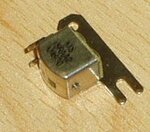
MS-15RAA2 tape head:

MS-15AA2.jpg
 
The cable to the head are for carrying the audio from the head when playing back and carrying the audio and bias to the head when recording.

Bre careful if you disconnect the head and use the cables as an audio input for several reasons:
1. If you hit 'record' you could feed quite a high voltage at around 20KHz into the cable and cause damage,
2. The signal level from the head is normally very small, only a few mV so normal 'line' level audio will overload the amplifiers badly.
3. The audio on a tape has pre-emphasis - the frequency distribution is deliberately skewed. To overcome this, the amplifier applies the opposite skew. If you feed a different audio source into the head wires, the signal will be un-skewed when it doesn't need to be and the tone will sound wrong.

Brian.
 

Hi guys,

Thanks for you answers.

Now I understand the four pins of the heads.

A closer look on the main board gives shows that the tape player uses ta2068n ic for reading these signals. So I saw which wires go to the inputs of this ic and I connected there the left and right signal.

As Brian says the sound is not very good (Brian you are right about your concerns). THe thing is where should I tamper it in order to do what I would like to???

Any ideas?

Thanks again
 

It really depends on what you are trying to achieve by doing this.

The TA2068 has four inputs, you might be able to utilize one of the others instead of the tape input. The tape head will connect to one input, the CD to another and I'm guessing a microphone to another as the IC has "Karaoke" mode. That leaves one unused input which will either be on pins 14 & 24 or on pins 16 & 22 (left & right channels). If these are unused, you should be able to hook them up to your new audio input sockets.

Brian.
 
I found I can send audio to a tape head by playing the audio into a coil, which I hold near the tape head.

It's a jerry-rig but there's no messing with wires or high voltage.

I think this principle is used in storebought 'converter units' that let you play a cd through your car's cassette player. These were marketed several years ago. Shaped exactly like an audio cassette, and came with a cable which you plugged into the cd player.

I had to test many coils before I found some that gave decent sound, and were the right impedance for line level devices.
 

I've made a few of these in the past. You will find best performance is obtained by using another tape head, mounted inside the cassette plastic case. You need to align it fairly carefully, especially the 'height' inside the cassette aperture so the L and R channels are close to the corresponding gap in the player's head or the channel separation will suffer.

Brian.
 

Hi guys,

First of all thank you all for giving your time to answer my questions.

Here is the progress I made and some results.

So reviewing the facts:

I am trying to replace the magnetic audio head with a stereo audio in jack.

I see that from the head four cables are leaving.
First is Ground and I think it is used as a ground shield for the cable.
Second goes to pin 8 of the TA2068 IC
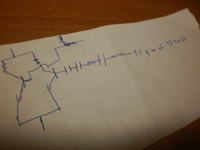
The third goes to tthe input of a transistor that affects indirectly pin 11 of TA2068 IC.(see image)
The fourth goes to pin 5 of the TA2068 IC

All pins of TA2068 IC are connected to something.

I cut the audio head.
I connected the left channel of the stereo cable to the second cable.
I connected the right channel of the stereo cable to the fourth cable.

NO SOUND

(the other cable as they were)
I connect the ground of the stereo jack to the first cable(ground)

NO SOUND

I disconnect the ground of stero jack from the first cable.(ground)
I short circuit third and second cable

SOUND WITH NOISE, WHEN I REMOVE THE JACK FROM THE MUSIC SOURCE THEN THE NOISE IS UNBEARABLE

I connect ground of stereo jack with first cable

NO SOUND

I disconnect the ground of stero jack from the first cable.(ground)
I connect the ground of stero jack to the second cable.

EXTREMELY LOUD SOUND WITH NOISE.

So that's what I have done so far. More it is somethjing like try and error. If someone knows analog and can explain and /or improve my circuit I would appreciated very.


SOUND WITH NOISE, WHEN I REMOVE THE JACK FROM THE MUSIC SOURCE THEN THE NOISE IS UNBEARABLE
...
I disconnect the ground of stero jack from the first cable.(ground)
I connect the ground of stero jack to the second cable.

EXTREMELY LOUD SOUND WITH NOISE.

Since these are the only time you get any sound, it's progress.

You probably need to attenuate the signal from line level down to a few milli-volts. A potentiometer (volume control) should do the job.
 

I 'll try with the potentiometer and I will post back.

What should I do with the ground of the stereo jac? Just leave it hanging? When I connect it to the boards ground the sound is eliminated.
 

What should I do with the ground of the stereo jac? Just leave it hanging? When I connect it to the boards ground the sound is eliminated.

Not sure how that would happen.

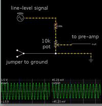
When I want to do similar type experiments I generally use a jumper at a convenient location on the chassis.

This is a typical arrangement:

 
Hello again,

So I tried with the potensiometers here are the results:

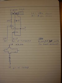
In the image attached you can find what my connections are.


With the above connections :
LC through the potensiometer to the LCP and following LCP at the board I see it goes to the 5th pin of TA2068
RC through the potensiometer to the RCP and following RCP at the board I see it goes to the 5th pin of TA2068
Stero jack's ground connected to the potensiometers

NO SOUND

Now when I short ciruit LCP and 3P I have sound at my left speaker
Now when I short ciruit RCP and 3P I have sound at my right speaker
If I short circuit alltogether LCP,RCP and 3P NO SOUND.

I tried connecting RCP to 3P when LCP is shortcircuited with 10K resistance but same result.

Any ideas why this is happening?
 
Last edited:

I do not see a ground connection to the board.

You may get sound at times, because one channel can find a path to ground through the other channel back to the source.

Is the sound no longer fuzzy and loud? If so then you're making progress.

I think you still need to jumper the board's ground to the junction which you labelled as a question mark.
 

Hi BradtheRad,

Thanks for your reply.

The ground connection to the board is marked as B_GND. When I connect the questionmark to B_GND sound is lost.

Yes the sound is no longer fuzzy :)!!!

I would jumper the board's ground to the junction labelled as a question mark but I forgot to mention that I did not understand what exactly do you mean by that.

Could you please explain?

Thank you in advance
 

The ground connection to the board is marked as B_GND. When I connect the questionmark to B_GND sound is lost.

Yes the sound is no longer fuzzy :)!!!

I would jumper the board's ground to the junction labelled as a question mark but I forgot to mention that I did not understand what exactly do you mean by that.

Could you please explain?

If you connect a wire from B_GND to the question mark, then you are jumpering the two points.

I suspect that you are still getting sound when you do that. Some ground connection is needed. The signal cannot carry on one wire connecting two pieces of equipment.

Perhaps the line level signal is softer than I thought. You may not need the 100k resistor in post #11. Try omitting it. Connect the wire directly to the potentiometer. That way you will get the full range of volume, from zero all the way to a loud and fuzzy signal.

By the way, you should measure volt level on the TA2068N's pin 5 and 8. It may be best if you do not connect them directly to ground (although I don't know for sure). That can happen when you dial the potentiometers to zero. It may be wise to install a series resistor between those pins and the potentiometer wiper terminals.
 

Hello all,

Sorry for the radio silence :)

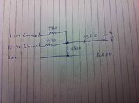
I managed to solve. A friend indicated that maybe one channel was cancelling the other so I converted the stereo to mono with the connections in the image.


For the noise I twisted carefully the ground around the signal cable and I removed a pot I had for volume control.

Thanks everybody for their help.
See you again in another project :)
 

Status
Not open for further replies.

Similar threads

Part and Inventory Search

Welcome to EDABoard.com

Sponsor

Back
Top