ferbo
Junior Member level 2
Hello everyone,
I am designing a charger power path manager with ltc4020. My input voltage is 35-50 v output is 40-50 volts. My output maximum current is 5 A and I have a 12s li-po battery.
this IC has a current sense resistor for the battery charging and two separate current senses for the inductor current. I am building my design based on the circuit on page 48 of datasheet.
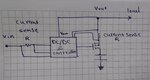
My question is that how does this IC control the charge current while simultaneously supplying the load? Is it possible that that it controls the current that passes through the P channel FET connected between the output and the battery?
Thank you for your help guys.
I am designing a charger power path manager with ltc4020. My input voltage is 35-50 v output is 40-50 volts. My output maximum current is 5 A and I have a 12s li-po battery.
this IC has a current sense resistor for the battery charging and two separate current senses for the inductor current. I am building my design based on the circuit on page 48 of datasheet.
My question is that how does this IC control the charge current while simultaneously supplying the load? Is it possible that that it controls the current that passes through the P channel FET connected between the output and the battery?
Thank you for your help guys.