Continue to Site

Welcome to EDAboard.com

Welcome to our site! EDAboard.com is an international Electronics Discussion Forum focused on EDA software, circuits, schematics, books, theory, papers, asic, pld, 8051, DSP, Network, RF, Analog Design, PCB, Service Manuals... and a whole lot more! To participate you need to register. Registration is free. Click here to register now.

LT1083/LM317 current limit to be make the regulator go down below 1.2V

Status
Not open for further replies.

xReM1x

Member level 5
Joined
Mar 25, 2014
Messages
83
Helped
0
Reputation
0
Reaction score
0
Trophy points
6
Activity points
586
hi, I'm desiging a power supply and there is what I have for start :
d4734602988a4913b3e30778ad415191.png

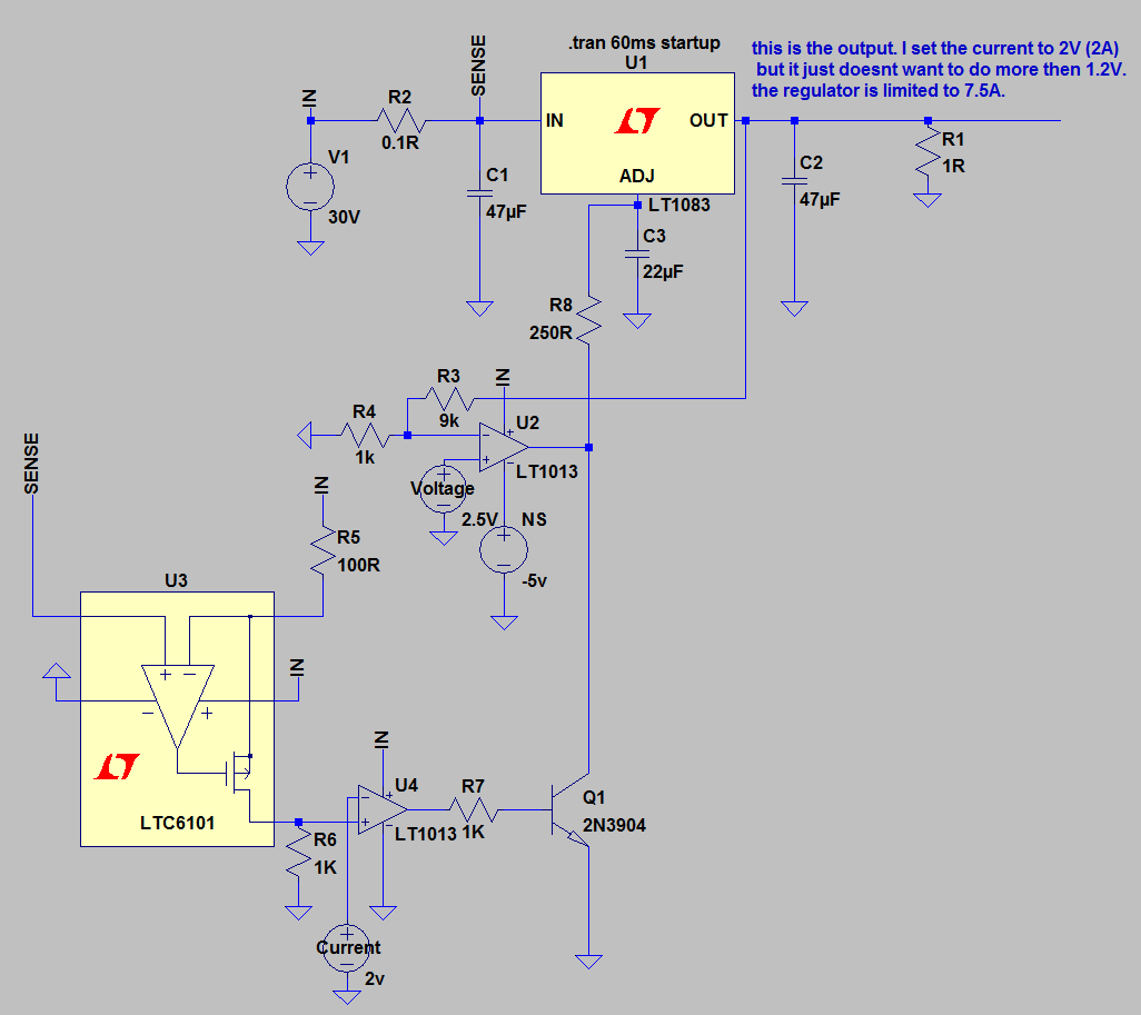
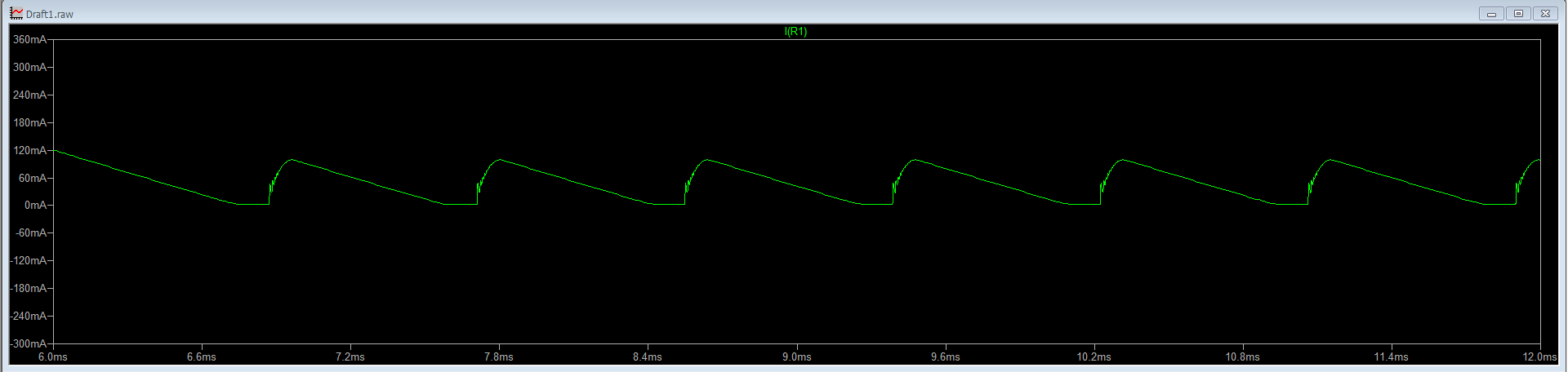
the problem is that the current limit shors the adj to ground and that makes the regulator go down to 1.2V instand of 0V. I cant use a constant voltage negative supply instand of ground because this voltage always need to be adjusted acording to the load.
so I taught about an op amp that constanly adjust the negative supply to make the set current = to the output current.
my question is how do I do that?
 

If the output is 1.2V/1R = 1.2A and your Vin is 30V your Pd in the series regulator is about 30W.

What is you design spec for output current and voltage?
 

If the output is 1.2V/1R = 1.2A and your Vin is 30V your Pd in the series regulator is about 30W.

What is you design spec for output current and voltage?
there will be pre regulator included, dont worry about those stuff, the problem is the current limiting.
output current - 0-5A
output voltage - 0-20V at least.
 

1) Current regulation gain is too high and saturates to ground. The loop gain and phase margin is important for step load stability too.
2) If can create -2.0V say using some other source then you connect the R divider Vadj to drive the output to 0V.

RED LEDs are good for 2.0V near 10~15mA and you might consider a charge pump inverter or some other convenient source.

The problem with this method is LDO"s are series pass and high impedance at 0V out , so a shunt regulator would improve this on the output. Essentially a Half bridge . But very inefficient. Thus a SMPS regulator is more efficient. There is no simple solution for your wide ranging requirement.
what current regulation gain?
2. I'm using a charge pump to create negative low current supply for those things. how exacly do I connect it?

I'm going to use other not low dropout regulator for those things, maybe even LM317 with extrenal pass transistor or LM723. will see
 

what current regulation gain?
2. I'm using a charge pump to create negative low current supply for those things. how exacly do I connect it?

I'm going to use other not low dropout regulator for those things, maybe even LM317 with extrenal pass transistor or LM723. will see


No V- on your schematic.
I suggested biasing -2V thru a red LED acting as a zener so your Vadj fixed voltage is increased by 2V and thus Voltage gain increases but offset so you can adjust to 0.

Your LTC6101 gives unity gain for V/I but then you have an inverting comparator and inverting transistor with massive gain and if Isense exceeds Iset, Vadj is pulled to ground and overpowers U2. in one direction only.
 

I would use the current limit IC (U3) to grab hold of the reference voltage on U2 pin + input, via a diode to pull the reference voltage negative. U2 output should then go to -5V ! I don't think you need U4 and Q1
Frank
 

No V- on your schematic.
I suggested biasing -2V thru a red LED acting as a zener so your Vadj fixed voltage is increased by 2V and thus Voltage gain increases but offset so you can adjust to 0.

Your LTC6101 gives unity gain for V/I but then you have an inverting comparator and inverting transistor with massive gain and if Isense exceeds Iset, Vadj is pulled to ground and overpowers U2. in one direction only.

I would use the current limit IC (U3) to grab hold of the reference voltage on U2 pin + input, via a diode to pull the reference voltage negative. U2 output should then go to -5V ! I don't think you need U4 and Q1
Frank

I did what you suggested with the diode and it works! expect will some oscilatiion!
when I set the current to 0.01A thats what I get when I zoom in:
f9785a2c99be13412a5b80ce777a4447.png
 

As SunnySkyguy mentioned, the current limiting control loop gain is too high. You have full LT1013 opne loop gain, multiplied with Q1 gain. You can't expect stable constant current operation without frequency compensation of the current control loop.
 

Status
Not open for further replies.

Part and Inventory Search

Welcome to EDABoard.com

Sponsor

Back
Top