Continue to Site

Welcome to EDAboard.com

Welcome to our site! EDAboard.com is an international Electronics Discussion Forum focused on EDA software, circuits, schematics, books, theory, papers, asic, pld, 8051, DSP, Network, RF, Analog Design, PCB, Service Manuals... and a whole lot more! To participate you need to register. Registration is free. Click here to register now.

lpc1768 core speed??

Status
Not open for further replies.
I don't think there is default clock for that like the mbed board, the clock can be whatever you program it to be in your code (within operating range for the mcu)
 

It's just that in the mbed online compiler the clock setting is hidden and it is set to 96MHz, when you program a board on your own you can set the clock to any value you want
 

So a user won't know what is the CPU clock when he powers the controller for the first time and Im using keil mdk arm version 5 when I go to configure flash tools there's a option which asks to fill up the xtal like what is it used for like if I write 100mhz would my sysclk work at 100mhz
 

So a user won't know what is the CPU clock when he powers the controller for the first time

If there is no code loaded it doesn't matter, if there is code loaded then the code sets the clock, it doesn't matter to the user what the clock is by default.

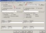
Im using keil mdk arm version 5 when I go to configure flash tools there's a option which asks to fill up the xtal like what is it used for like if I write 100mhz would my sysclk work at 100mhz

You seem to refer to

Snap1.jpg

but as you see it has nothing to do with changing the cpu core frequency

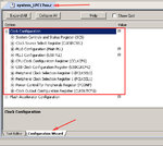
The core clock (and peripheral clocks) can be set from the configuration wizard of system_LPC17xx.c

Snap2.jpg
 
thanks a lot alexan i actually migrated from avr to arm processor so was bit confused as in avr i used 16mhz crystal i knew the core would run at 16mhz but in case of arm u need to set core speed by yourself :smile: i learnt
 

i written this code to set core speed to 100mhz is it right
Code:
[CODE]#include "LPC17XX.h"


 int main()
 {
 SystemCoreClock=100;
	 SystemInit ();
	

 }
[/CODE]
and another problem is that while simulating i single step and get stuck in this loop forever
while (!(LPC_SC->PLL0STAT & (1<<26)));/* Wait for PLOCK0
(please dont mind if the qusetion is annoying i am a beginner :))
 
Last edited:

That variable reflects the current core clock and in intended to be read, not written. Even if you write to it the clock doesn't change
https://www.keil.com/pack/doc/cmsis/core/html/group__system__init__gr.html

Have you included system_LPC17xx.c?
Open the example located C:\Keil\ARM\Boards\Keil\MCB1700\Blinky , that is set to 100MHZ so look at the values used in the configuration wizard (as shown in post #8 above).

To verify your clock you can run the simulator and open
Snap1.jpg

You may also find this thread useful https://www.edaboard.com/threads/273242/
In post #36 you can find the equation for the core clock
 

thank you alexan for your reply,i understood the formula have set the parameters accordingly manually as im not getting dialog box as you are getting im using keil mdk arm version 5 .Now i have written a program which configures pll
Code:
void setpll()
{
// the crystal oscillator is 12 MHz
// main oscillator frequency 300 MHz: M = (300 x N) / (2 x 12)
n=2;
m=25;
// processor clock 100 MHz = 300 MHz / D
d=3;
// disconnect
LPC_SC->PLL0CON=0x00000001; pllfeed();
// disable
LPC_SC->PLL0CON=0x00000000; pllfeed();
// set new PLL values
LPC_SC->PLL0CFG=((n-1)<<16)|(m-1); pllfeed();
// enable
LPC_SC->PLL0CON=0x00000001; pllfeed();
// set cpu clock divider
LPC_SC->CCLKCFG=d-1;
// wait for lock
while (LPC_SC->PLL0STAT&0x04000000==0);
// connect
LPC_SC->PLL0CON=0x00000003; pllfeed();
}
 
void pllfeed()
{
__disable_irq();
LPC_SC->PLL0FEED=0x000000aa;
LPC_SC->PLL0FEED=0x00000055;
__enable_irq();    
}
i simulate(single step) the code and get stuck at
while (LPC_SC->PLL0STAT&0x04000000==0);
how to bypass this loop
 

thanks alexan the code is right i confirmed the problem is with simulation like one of the condition consists of read only register(PLL0STAT) it is iset in hardware only
while (LPC_SC->PLL0STAT&0x04000000==0);
so how can i simulate it in software like this condition will be true in software always
 

As I said I have only used system_LPC17xx.c to set the clock and never had a problem in simulation, I can't answer about the way you are trying to use but you can check system_LPC17xx.c to see how they do it.
 

i have included the system_lpc17xx in my program now when i begin simulation the cursor runs onto the system_lpc17xx.c file rather than my application code is it right
(and surprisinglywhen i simulate system_lpc17xx.c the core clock is 100mhz)
 

At boot the mcu runs the startup code that calls systemInit and then main so the behaviour you describe is correct.

Code:
Reset_Handler   PROC
                EXPORT  Reset_Handler             [WEAK]
                IMPORT  SystemInit
                IMPORT  __main
                LDR     R0, =[COLOR="#FF0000"]SystemInit[/COLOR]
                BLX     R0
                LDR     R0, =[COLOR="#FF0000"]__main[/COLOR]
                BX      R0
                ENDP

The execution stays a while inside SystemInit() but you can use step out and the code will run until it returns to startup and then with a few steps it will enter main

I usually check the run to main checkbox and debug starts in the first line of main without having to go through all the previous steps.

Snap1.jpg

An alternative is to use a breakpoint in main and run until execution goes there.
 

Status
Not open for further replies.

Similar threads

Part and Inventory Search

Welcome to EDABoard.com

Sponsor

Back
Top