v.s.n.kumar
Member level 1

- Joined
- Dec 2, 2013
- Messages
- 38
- Helped
- 0
- Reputation
- 0
- Reaction score
- 0
- Trophy points
- 6
- Activity points
- 303
Hi,
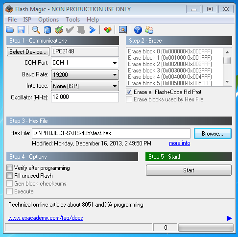
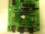
I have been facing the problem with the lpc2148 development board from the day i bought it. There is BOOT button & RESET button. when i start to dump the program in to it, the flash magic showed ''Failed to read the device signature". so by pressing the boot button continously & i start dumping the code, then only flash magic shows me ''Finished". I have dumped serial communication program. the code is what ever the letters that we press from key board that must appear on the hyper terminal of the pc. this is working perfectly. below code is the serial communication code. The main problem is if i dump another code like led blinking, then also the below serial communication code is working if i open the hyper terminal & type the letters then they appear on the hyper terminal of the pc. i.e., the actual code is not working(what ever the code i dumped, the below serial communication code is working instead of the dumped codes). please solve my problem. i have exam on the arm. please solve. i post the serial communication code, led blinking code & images of the board. can anybody please solve my problem.
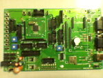
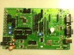
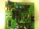
I have been facing the problem with the lpc2148 development board from the day i bought it. There is BOOT button & RESET button. when i start to dump the program in to it, the flash magic showed ''Failed to read the device signature". so by pressing the boot button continously & i start dumping the code, then only flash magic shows me ''Finished". I have dumped serial communication program. the code is what ever the letters that we press from key board that must appear on the hyper terminal of the pc. this is working perfectly. below code is the serial communication code. The main problem is if i dump another code like led blinking, then also the below serial communication code is working if i open the hyper terminal & type the letters then they appear on the hyper terminal of the pc. i.e., the actual code is not working(what ever the code i dumped, the below serial communication code is working instead of the dumped codes). please solve my problem. i have exam on the arm. please solve. i post the serial communication code, led blinking code & images of the board. can anybody please solve my problem.


Code C - [expand]
Last edited by a moderator:

