PG1995
Full Member level 5
Hi
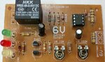
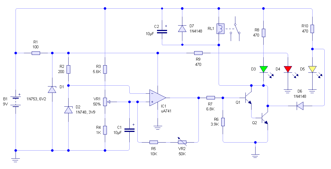
I think **broken link removed** circuit is used to cutoff the voltage source to the output if it's the voltage is 6V or lower. Do I have it correct? I googled "6v low voltage cutoff" and found **broken link removed** somewhat similar looking circuit.
The red LED is for power indication in the circuit and the white LED is for low voltage indication.
Is that component on the top left a relay?
What is that IC on the top right? Someone was saying that the circuit uses operational amplifier. But someone said it could be a LM393 dual comparator. What do you think?
In what kind of applications this circuit can be used? Could you please list some examples of circuits or electronic products which can be damaged by low voltage if they don't use such voltage cutoff circuit.
Thank you for the help.
Regards
PG