Continue to Site

Welcome to EDAboard.com

Welcome to our site! EDAboard.com is an international Electronics Discussion Forum focused on EDA software, circuits, schematics, books, theory, papers, asic, pld, 8051, DSP, Network, RF, Analog Design, PCB, Service Manuals... and a whole lot more! To participate you need to register. Registration is free. Click here to register now.

low power FM Transmitter

Status
Not open for further replies.

mr_byte31

Full Member level 5
Joined
Oct 19, 2005
Messages
295
Helped
10
Reputation
20
Reaction score
8
Trophy points
1,298
Activity points
3,241
Hi All,

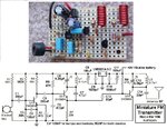
I made some search on the internet regarding simple FM transmitters.

I found those circuits :

Fm-transmitter-Copy.jpg


miniature-FM-transmitter.png


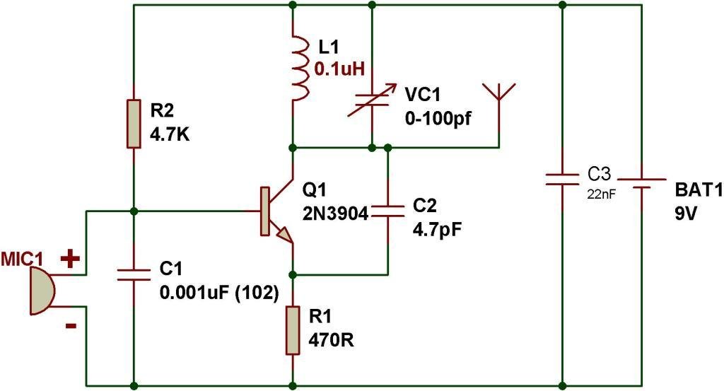
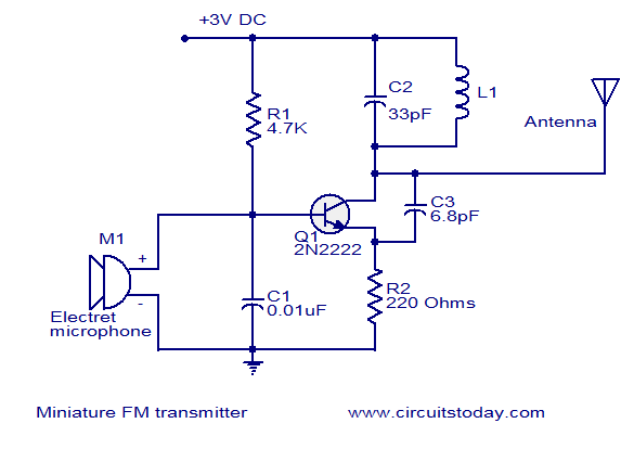
They all have the same layout but different values.
I want to understand the concept of the capacitor that is connected between the collector and emitter , it seems it is the main idea of the fm modulation but i dont understand how.
I would like to know how to determine its value
 

C2/C3 is a feedback capacitor for oscillator.Its value is found by a serious math or directly simulation but it's probably been found here by try-and-see method.
These FM transmitters will perhaps work but I'm afraid you will have to speak very loudly--))
 

it is very hard then to define the capacitance by trial and error :(
the input would be computer so i dont need amplifier
 

You can use a simple spice simulator and look at the open-loop gain/phase response to get an idea of value of C3 needed.

For the last schematic in your post, you can see that C3 needs to be above 4 pF to satisfy the criteria (gain of 8-12 dB to phase zero) for oscillations. If you make C3 too large, then you may get other problems like oscillator squegging. The load of the antenna will also influence the value of C3.

- - - Updated - - -

When C3 is too small it will not start.
 

Attachments

  • gain_phase.png
    gain_phase.png
    41.8 KB · Views: 92
  • osc_start.png
    osc_start.png
    17.1 KB · Views: 85
  • no_start.png
    no_start.png
    15 KB · Views: 82
Last edited:
In the first circuit, the 4.7k value of R2 that biases the transistor is very low and the 470 ohms value of R1 the emitter resistor is fairly high so I think the transistor will be saturated and will not oscillate.

For a regulated 5V supply, my FM transmitter uses 47k for R2 and 220 ohms for R1. The inductor and RF capacitors are the same as this simple circuit. It has a 5V low-dropout voltage regulator so that the frequency doesn't change and so that the preamp still works as the battery voltage runs down. The preamp has gain and pre-emphasis (treble frequencies boost) like real FM radio stations so that the de-emphasis (treble frequencies and hiss cut) in all FM radios does not cause the sound to be muffled like in this simple circuit shown here.

EDIT: FM modulation fluctuates the radio frequency with the audio. The audio causes the transistor to fluctuate its current then its capacitance also fluctuates which fluctuates the frequency producing FM. The circuit also produces amplitude fluctuations (AM) but FM radios ignor AM.
 
Last edited:
Thanks all for the greet support.

I started to feel that most of the circuits over internet might not work as expected.

I found this circuit and its author said it is tested :

Capture.PNG

the C5 has value = 10 PF which would give good gain.

Now , i think about if there is a possibility that oscillation circuit would work or not or sometimes?
it is very hard after i connect the circuit to know if the oscillator works or not !!
 

The circuit will work if it is built on a pcb or stripboard with the traces cut short. It probably will not work on a solderless breadboard.

It will have the following problems:
1) Its oscillator does not have a voltage regulator so its radio frequency will change as the battery voltage runs down.
2) It is missing pre-emphasis so the de-emphasis in all fM radios will cut high audio frequencies making it sound like a telephone or an AM radio.
 
Here is my FM transmitter. It has a low-dropout 5V voltage regulator, it also has an RF amplifier so that the dropping battery voltage or anything moving toward or away from the antenna does not change its RF frequency.
Its preamp makes it very sensitive to sounds. It sounds great because it has pre-emphasis like FM radio stations.
Its range is more than 2km to a very sensitive home stereo or car radio across a large river valley or about 300meters down the street to a Sony Walkman FM radio or across the street to a cheapo FM radio from The Dollar Store. I think its range is about 200 meters to a cheapo clock radio.
 

Attachments

  • FM tx mod4 pic and schematic.jpg
    FM tx mod4 pic and schematic.jpg
    196 KB · Views: 90
Status
Not open for further replies.

Part and Inventory Search

Welcome to EDABoard.com

Sponsor

Back
Top