Continue to Site

Welcome to EDAboard.com

Welcome to our site! EDAboard.com is an international Electronics Discussion Forum focused on EDA software, circuits, schematics, books, theory, papers, asic, pld, 8051, DSP, Network, RF, Analog Design, PCB, Service Manuals... and a whole lot more! To participate you need to register. Registration is free. Click here to register now.

Low-Pass filters in series, does it work?

Status
Not open for further replies.

AlephUser

Newbie level 4
Joined
Jan 2, 2014
Messages
6
Helped
0
Reputation
0
Reaction score
0
Trophy points
1
Activity points
69
Hey there, I'm working on a project where I need to take a signal and "separate" it into three small signal bands. As I'm working it right now:

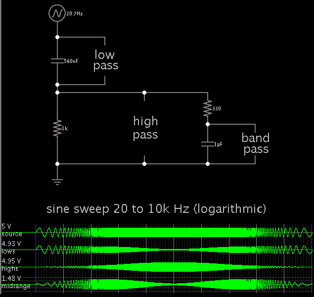
I have a signal +S. In series, there's a resistor R1, a resistor R2 and a capacitor C2. But, between R1 and R2 there's a node with another capacitor, C1, connected in the ground.

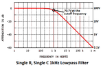
The idea is that the mash S ~ R1 ~ C1 ~ GND forms a low pass filter. So the voltage at R1 would be the higher harmonics of S1.

In contrast, the voltage at C1 would represent the other harmonics, because it's E - VR1.

But as C1 is in parallel with the mash R2 ~ C2 ~ GND then this would form a second filter with input voltage VC1.

Then, VR2 would again represent the higher harmonics, but as the first filter already got the highest harmonics, VR2 would represent median harmonics.

Finally, the lowest harmonics would be in VC2.


That principle sounded okay at my mind, but I wasn't so sure so I googled around for "Low-Pass Filter in Series" and stuff like that. The problem is: I didn't managed to find anything. When I learned filters I didn't used notations as grounds and didn't needed concepts like harmonics. So I really don't know if that idea is right or if it's wrong. Could you guys help me?

Notes: I'll try to draw the scheme and post it here as soon as possible. Also, I'm trying to work with an audio signal amplifier project, so any ideas are welcome!


Thanks in advance!
 

A single RC filter has a gradual slope. Its output is -3dB at its cutoff frequency.
Two RC filters in series have the second one loading down and affecting the first one.
Two RC filters with a buffer between them have a droopy response that is -6dB at its cutoff frequency. Frequencies far from the cutoff frequency are affected.

A Sallen-Key active filter uses an opamp to add some positive feedback at the cutoff frequency so a Butterworth filter has a flat response then a sharp corner then a steep slope.

- - - Updated - - -

For 3 frequency bands then the middle band needs a bandpass filter, the low frequency band needs a lowpass filter and the high frequency band needs a highpass filter.
 
Last edited:

Sorry, we didn't had any "deep" look at filters, just an introductory matter, so I don't know the differences between Butterworth filters, Sallen-Key filters and stuff like that =\

2014-01-06 17.07.44.jpg
Here, there's my circuit design. From what I know the single input signal (that's S in the scheme) can be understood as several senoidals superposed, like this:
2014-01-06 17.16.33.jpg
What I want is that the voltage at R1 to "hold" the highest frequencies of the signal while the voltages at R2 to "hold" the middle frequencies and the voltage at C2 to "hold" the low frequencies, in other words, the other ones...
Is my development with the RC filters right?
 

You do not have a clue about filters. Also your English does not make sense.

A LOWPASS filter passes low frequencies. It REDUCES the level of high frequencies. The higher is the frequency then the more its level is reduced.
How on earth can it HOLD a high frequency that has its level reduced?? How can anything HOLD a frequency??

R2 also does not HOLD anything and certainly not middle frequencies. Instead R2 and C2 reduce the level of high frequencies even more than R1 and C1.
Your R1C1 combined with R2C2 filter works as a very poor lowpass filter.

Please try to explain what frequencies you want the filter to pass and what frequencies you want it to reduce.
 

Haha, sorry, my english is really bad! And to tell the truth I didn't learnt but about filters because my teacher used to throw the formulas in the blackboard and make us try to figure out ourselves what it was. (Actually, I'm having to redo this discipline).

What I'm trying to say is that:
When you have a regular RC lowpass you have an input signal, a resistor and a capacitor, like this:
**broken link removed**

And as in any circuit you have some voltage "over" the resistor and capacitor, like this:
**broken link removed**

From Kirchhoff we can then say:
VR = S-Vo
VC = Vo

Where VR is the voltage "over" the resistor and VC is the voltage "over" the capacitor.
Now, that's how I was explained the working of that:

When you have a frequency lower than the cuttof frequency as the input then the voltage "over" the resistor is minimal and the voltage "over" the capacitor is ideally equal the input voltage.
When you have a frequency higher than the cuttof frequency as the input then the voltage "over" the resistor is maximal and the voltage "over" the capacitor is ideally equal zero.

Now, is that how RC filters works, right?


Also, sorry for the bad-quality images and the bad english. I don't have a clue on how electronics terminology works for english, and if I were to literaly translate how we speak in portuguese I would be saying "tension on the resistor". I guess that's really bad so I tried to adapt it as "voltage over the resistor". Note that I used quotation marks (in "over" and "hold" on my previous post) to denote I knew it was wrong but had no better term... So well, sorry!
 

Your attachments do not work.

Why doesn't your lazy teacher teach you this stuff instead of having you guess WRONGLY about it?

An RC lowpass filter has the signal source feeding a resistor that feeds the output and a capacitor to ground.
When the frequency is much less than the cutoff frequency and the load has an impedance much higher than the resistor value then the level of the signal source appears at the output (because the capacitor does not affect very low frequencies).

When the frequency of the signal source is higher than the cutoff frequency then it is reduced in level to 1/10th each time the frequency is 10 times higher. It is a VERY simple filter so a lot of the high frequency power is still there. The level of only VERY high frequencies will be zero.

Here is its response curve found in Google. The cutoff frequency of this filter is 1kHz and the level is 70.7% of the input level. But 500Hz is also reduced a little.
10kHz is at 10% of the input level, 100kHz is at 1% of the input level and 1MHz is at 0.1% of the input level. Higher frequencies are reduced more.
 

Attachments

  • lowpass filter response curve.png
    lowpass filter response curve.png
    16.2 KB · Views: 146

Starting with your descriptions of the RC filters, I experimented with simulations.

You can obtain midrange frequencies by tapping across the correct component of the final RC network. (The amplitude is greatly reduced, as Audioguru states.)

In the first RC network...
Low frequencies appear across the capacitor. Highs appear across the resistor.

Phase changes are in the nature of the animal here.

You can adjust values in the second RC network to move the center frequency up or down (within limits).


Here's the frequency response of the voltage across each component, assuming R1=R2 and C1=C2.


To design filters you must read some books or articles to build up understanding of it otherwise you will never understand what is going on. I personally find Analog and Digital Filter Design by Steve Winder a very good book.

Also, I would recommend you to start using simulators. There are many free simulators available on the net for e.g LTspice.
 

To design filters you must read some books or articles to build up understanding of it otherwise you will never understand what is going on. I personally find Analog and Digital Filter Design by Steve Winder a very good book.
Also, I would recommend you to start using simulators. There are many free simulators available on the net for e.g LTspice.

AlephUser, yes - I support these recommendations.
More than that, I`ve got the impression that at first you should try to become familiar with the concept of frequency-dependent impedances (magnitude, phase, 1/jwC)
 

Hey there guys! Sorry for the late reply, but I was very busy!
I got a little surprised on how many answers my thread had when I saw it haha!
Those all helped very much, and I even favorited this thread for future references! I'll try to read some books and learn more about filters, but be sure your answers greatly helped me! Thanks!
 

Status
Not open for further replies.

Similar threads

Part and Inventory Search

Welcome to EDABoard.com

Sponsor

Back
Top