Continue to Site

Welcome to EDAboard.com

Welcome to our site! EDAboard.com is an international Electronics Discussion Forum focused on EDA software, circuits, schematics, books, theory, papers, asic, pld, 8051, DSP, Network, RF, Analog Design, PCB, Service Manuals... and a whole lot more! To participate you need to register. Registration is free. Click here to register now.

low pass Filter calculation

Status
Not open for further replies.

antriksh

Newbie level 6
Joined
Aug 3, 2013
Messages
13
Helped
1
Reputation
2
Reaction score
1
Trophy points
3
Activity points
93
filter.png

Hi,

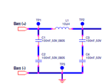
we have a design of a low pass CLC filter in our power circuit as attached. does any one know the calculation for this filter.

how do we calculate this filter why do we required this type of filter. how the values of L and C are selected.

Please help me to understand the filter calculation

Thanks in advance....
 

Hi,

if you consider, that the source is on the left side with zero impedance, then you may omit C1, C2.

C3, C4 can be combined as a single capacitor of 50nF.

Now you have a simple LC low pass filter (resonance) with 100uH and 50nF.

Klaus
 

It is simple Pi-filter:

The source capacitor offers low reactance to the AC component of the rectifier output while it offers infinite resistance to the DC component. As a result the capacitor shunts an appreciable amount of the AC component while the DC component continues its journey to the inductor.

The inductor offers high reactance to the AC component but it offers almost zero resistance to the DC component. As a result the DC component flows through the inductor while the AC component is blocked.


The load capacitor bypasses the AC component which the inductor had failed to block. As a result only the DC component appears across the load.

You just need to find the equivalent values of the capacitors.

check wikipedia for further details
 

The two 100nF capacitors in series produce 50nF of capacitance.
Then simply calculate the cutoff frequency of the inductance with this capacitance.
I think the load produces an interference signal that this filter prevents from spreading to other circuits powered by the battery. The battery does not produce the interference signal, it simply passes the interference if there is no filter.
 

Status
Not open for further replies.

Similar threads

Part and Inventory Search

Welcome to EDABoard.com

Sponsor

Back
Top