Sajjadkhan
Full Member level 5

- Joined
- Sep 25, 2010
- Messages
- 307
- Helped
- 17
- Reputation
- 34
- Reaction score
- 16
- Trophy points
- 1,298
- Location
- Rawalpindi,Pakistan
- Activity points
- 4,199
I want to design a simple precision DC electronic load as those of Bk precision are expensive and they are actually when you think you can build one.
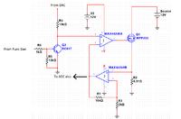
AS you can see in the fig i am using MAX44248 because i have already ordered them.I am not using direct feedback to the op-amp1 but via op-amp2 (gain of 10). Reason is so that i dont have to divide the DAC voltage on +ive input of opamp1.
A transistor at op-amp1 so that i can hook up fun gen to make pulse current.
This load will sink up to 20 Amps and (using multiple fets) and resolution of 1mA.
The opamp has the Vos of 10uV (worst case). so need to know about layout design as i have never designed with such low precision ic.
I know there would be thermocouple effects and ground loop problem, i am currently reading about them. I am designing this on home made PCB (i can design quite neat PCB).
Any suggestions for what i know and i dont know.

