Felis_Silvestris
Junior Member level 2
- Joined
- Dec 27, 2007
- Messages
- 23
- Helped
- 4
- Reputation
- 8
- Reaction score
- 4
- Trophy points
- 1,283
- Location
- San Jose, CA
- Activity points
- 1,517
waveguide filter design
Hi,
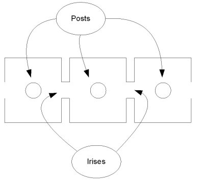
I am interested in learning more about designing a microwave cavity filter that utilizes a structure quite similar to a commonly found waveguide band pass filter using shunt inductance coupling (to couple resonators) (see [1] and [2]). However, the structure I am interested in also contains a post centered between the coupling irises with only one end connected to ground, the other end is a gap (capacitive)
I can tell that this structure operates (or can operate) in TEM mode and therefore is nothing more than a coaxial transmission line shorted at one end with a series capacitance across the other end.
I would like to find a book that discusses and uses this structure as an example to design this type of BPF.
I suspect that the structure I am curious about is used when the desired center frequency is low and therefore the posts help to reduce the size of the waveguide (am an not certain of this however so I could be wrong on that assumption.).
I have found a useful book that walks one through many specific examples [2], but I did not find one that goes over the exact structure that I am interested in.
I will attempt to embed a graphic showing the BPF structure that I am interested in. The embedded sketch is located on my pbase account and is a 2D drawing in the x-z plane; where z is the direction of energy and x is the “a” dimension of the waveguide. In this sketch the “b” dimension of the waveguide comes out of the page (or is normal to the page). Also, for TE10 the b direction (normal to the page) is the same direction as the E field for TE10 (or dominant mode).
If the graphic did not embed then look here: https://www.pbase.com/dstraight/image/102770330/medium.jpg
Regards,
David
[1] see figure 9.05-3 on page 540 of “Microwave Filters, Impedance-Matching Networks, and Coupling Structures” by Matthaei, Young and Jones
[2] Figure 9.12 on page 544 of “Electronic Filter Simulation & Design” by Giovanni Bianchi and Roberto Sorrentino.
[3] “Handbook of Filter Synthesis ” by Anatol I. Zverev
Hi,
I am interested in learning more about designing a microwave cavity filter that utilizes a structure quite similar to a commonly found waveguide band pass filter using shunt inductance coupling (to couple resonators) (see [1] and [2]). However, the structure I am interested in also contains a post centered between the coupling irises with only one end connected to ground, the other end is a gap (capacitive)
I can tell that this structure operates (or can operate) in TEM mode and therefore is nothing more than a coaxial transmission line shorted at one end with a series capacitance across the other end.
I would like to find a book that discusses and uses this structure as an example to design this type of BPF.
I suspect that the structure I am curious about is used when the desired center frequency is low and therefore the posts help to reduce the size of the waveguide (am an not certain of this however so I could be wrong on that assumption.).
I have found a useful book that walks one through many specific examples [2], but I did not find one that goes over the exact structure that I am interested in.
I will attempt to embed a graphic showing the BPF structure that I am interested in. The embedded sketch is located on my pbase account and is a 2D drawing in the x-z plane; where z is the direction of energy and x is the “a” dimension of the waveguide. In this sketch the “b” dimension of the waveguide comes out of the page (or is normal to the page). Also, for TE10 the b direction (normal to the page) is the same direction as the E field for TE10 (or dominant mode).
If the graphic did not embed then look here: https://www.pbase.com/dstraight/image/102770330/medium.jpg
Regards,
David
[1] see figure 9.05-3 on page 540 of “Microwave Filters, Impedance-Matching Networks, and Coupling Structures” by Matthaei, Young and Jones
[2] Figure 9.12 on page 544 of “Electronic Filter Simulation & Design” by Giovanni Bianchi and Roberto Sorrentino.
[3] “Handbook of Filter Synthesis ” by Anatol I. Zverev