Continue to Site

Welcome to EDAboard.com

Welcome to our site! EDAboard.com is an international Electronics Discussion Forum focused on EDA software, circuits, schematics, books, theory, papers, asic, pld, 8051, DSP, Network, RF, Analog Design, PCB, Service Manuals... and a whole lot more! To participate you need to register. Registration is free. Click here to register now.

Logic Timing Speed controlled by Power supply voltage?

Status
Not open for further replies.

PrescottDan

Banned
Joined
May 1, 2014
Messages
119
Helped
0
Reputation
0
Reaction score
0
Trophy points
16
Activity points
0
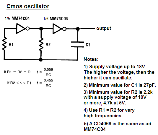
A Timer circuit, Oscillator circuit or a Clock circuit output a TTL logic signals

When the Power supply voltages varies higher , the output of the Timing signal gets Faster

When the power supply voltage varies lower, the output of the timing signal gets slower

Why does this happen?

What else can cause the Timing signals to get faster or slower?
 

Without knowing anything about your circuit, there's no way to answer your question. EVERYTHING can affect your timing: Temperature, humidity, magnetic fields, electric fields...
 

TTL gates (real LSTTL, bipolar transistors) are biased
by pullup resistors internally, your available operating
current goes something like (Vcc-3*Vbe) for the front
end and (Vcc-2*Vbe) for the back end (this, from 20+
years ago when we actually still designed LSTTL parts).
Risetimes are C/I roughly and delays, risetime/2 plus a
little lag.

Old TI databooks used to show LSTTL gate "guts" if
your interest extends beyond the "gimme" question.

Nowadays CMOS I/Os are still spec'd to be "TTL compatible"
without involving any actual BJTs. Here, CMOS drive strength
goes as (Vdd-Vth)^2, same remarks about rise and delay
times.
 

Many clocks that are RC based such as the old Dual VCO TTL were supply sensitive because they were design to be Voltage controlled. The same is true of many one shots etc.

Crystal oscillators will change frequency with supply due to input capacitance changing with supply voltage by a slight amount.

Some clocks use constant current source relaxation oscillators such as internal clocks for uC and 555 timers, but there will always be some sensitivity due to limitations vs simplicity.

If you have a need for Frequency supply stability, please identify the requirement or specific issue.

TTL also runs faster when hot for rise time , bandwidth and toggle rates for asynchronous operations.
CMOS runs slower when hotter.

Logic runs faster with higher voltage unless self heating in CMOS reduces speed with higher self heating.

The crux of engineering design is to use the fundamentals to learn the non-ideal characteristics of all parts with respect to climate, mechanical shock & vibe, altitude, etc, which requires mechanical engineering skill and sometimes, chemistry, RF awareness and transmission line theory.
 

A very simple oscillator made with two Cmos inverters has a stable frequency when the supply voltage changes.
A 555 oscillator also has a stable frequency when the supply voltage changes.
Here is the simple Cmos oscillator:
 

Status
Not open for further replies.

Similar threads

Part and Inventory Search

Welcome to EDABoard.com

Sponsor

Back
Top