yefj
Advanced Member level 4
Hello ,in the example shown bellow our interrupt is defind as
GPIO_ExtIntConfig(BSP_GPIO_PB0_PORT, BSP_GPIO_PB0_PIN,BSP_GPIO_PB0_PIN, 0, 1, true);
BSP_GPIO_PB0_PORT=gpioPortF
BSP_GPIO_PB0_PIN=6
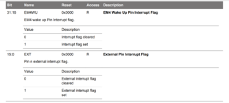
The intersting part comes for the intNo parameter we put BSP_GPIO_PB0_PIN which is six so we set it to be interrupt number 6.
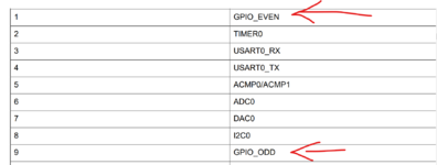
Interrupt number 6 is RAQ_seq_irq ,maybe there is a mistake in the example?
What is the logic when defining intNo parameter of the interrupt.
Thanks.
Interrupt notes:
Code:
/***************************************************************************//**
 * @file main_s1.c
 * @brief This project demonstrates a using GPIOs to trigger external
 * interrupts. When PB0 or PB1 is pressed, LED0 or LED1 is toggled,
 * respectively. See readme.txt for details.
 *******************************************************************************
 * # License
 * <b>Copyright 2020 Silicon Laboratories Inc. www.silabs.com</b>
 *******************************************************************************
 *
 * SPDX-License-Identifier: Zlib
 *
 * The licensor of this software is Silicon Laboratories Inc.
 *
 * This software is provided 'as-is', without any express or implied
 * warranty. In no event will the authors be held liable for any damages
 * arising from the use of this software.
 *
 * Permission is granted to anyone to use this software for any purpose,
 * including commercial applications, and to alter it and redistribute it
 * freely, subject to the following restrictions:
 *
 * 1. The origin of this software must not be misrepresented; you must not
 *    claim that you wrote the original software. If you use this software
 *    in a product, an acknowledgment in the product documentation would be
 *    appreciated but is not required.
 * 2. Altered source versions must be plainly marked as such, and must not be
 *    misrepresented as being the original software.
 * 3. This notice may not be removed or altered from any source distribution.
 *
 *******************************************************************************
 * # Evaluation Quality
 * This code has been minimally tested to ensure that it builds and is suitable
 * as a demonstration for evaluation purposes only. This code will be maintained
 * at the sole discretion of Silicon Labs.
 ******************************************************************************/

#include "em_device.h"
#include "em_chip.h"
#include "em_cmu.h"
#include "em_emu.h"
#include "em_gpio.h"
#include "bsp.h"

/**************************************************************************//**
 * @brief GPIO Even IRQ for pushbuttons on even-numbered pins
 *****************************************************************************/
void GPIO_EVEN_IRQHandler(void)
{
  // Clear all even pin interrupt flags
    uint32_t res;
    res=GPIO_IntGet();
    GPIO_IntClear(0x5555);

  // Toggle LED0
  GPIO_PinOutToggle(BSP_GPIO_LED0_PORT, BSP_GPIO_LED0_PIN);
}

/**************************************************************************//**
 * @brief GPIO Odd IRQ for pushbuttons on odd-numbered pins
 *****************************************************************************/
void GPIO_ODD_IRQHandler(void)
{
  // Clear all odd pin interrupt flags
  GPIO_IntClear(0xAAAA);

  // Toggle LED01
  GPIO_PinOutToggle(BSP_GPIO_LED1_PORT, BSP_GPIO_LED1_PIN);
}

/**************************************************************************//**
 * @brief GPIO initialization
 *****************************************************************************/
void initGPIO(void)
{
  // Enable GPIO clock
  CMU_ClockEnable(cmuClock_GPIO, true);

  // Configure PB0 and PB1 as input with glitch filter enabled
  GPIO_PinModeSet(BSP_GPIO_PB0_PORT, BSP_GPIO_PB0_PIN, gpioModeInputPullFilter, 1);
  GPIO_PinModeSet(BSP_GPIO_PB1_PORT, BSP_GPIO_PB1_PIN, gpioModeInputPullFilter, 1);

  // Configure LED0 and LED1 as output
  GPIO_PinModeSet(BSP_GPIO_LED0_PORT, BSP_GPIO_LED0_PIN, gpioModePushPull, 0);
  GPIO_PinModeSet(BSP_GPIO_LED1_PORT, BSP_GPIO_LED1_PIN, gpioModePushPull, 0);

  // Enable IRQ for even numbered GPIO pins
  NVIC_EnableIRQ(GPIO_EVEN_IRQn);

  // Enable IRQ for odd numbered GPIO pins
  NVIC_EnableIRQ(GPIO_ODD_IRQn);

  // Enable falling-edge interrupts for PB pins
  GPIO_ExtIntConfig(BSP_GPIO_PB0_PORT, BSP_GPIO_PB0_PIN,BSP_GPIO_PB0_PIN, 0, 1, true);
  GPIO_ExtIntConfig(BSP_GPIO_PB1_PORT, BSP_GPIO_PB1_PIN, BSP_GPIO_PB1_PIN, 0, 1, true);
}

/**************************************************************************//**
 * @brief  Main function
 *****************************************************************************/
int main(void)
{
  // Chip errata
  CHIP_Init();

  // Initializations
  initGPIO();

  while (1){
    // Enter Low Energy Mode until an interrupt occurs
    EMU_EnterEM3(false);
  }
}

