Continue to Site

Welcome to EDAboard.com

Welcome to our site! EDAboard.com is an international Electronics Discussion Forum focused on EDA software, circuits, schematics, books, theory, papers, asic, pld, 8051, DSP, Network, RF, Analog Design, PCB, Service Manuals... and a whole lot more! To participate you need to register. Registration is free. Click here to register now.

Load suggestions for 24V linear power supply prototype

Status
Not open for further replies.

Sorcha

Newbie level 1
Newbie level 1
Joined
Mar 13, 2013
Messages
1
Helped
0
Reputation
0
Reaction score
0
Trophy points
1,281
Visit site
Activity points
1,293
I'm finishing up my electronics technology degree, and I'm trying to do my projects really well so I can use them as a sort of portfolio for future job interviews.

Right now I am making a 24V regulated linear power supply with variable resistance. What would you suggest for my load that would showcase its functioning? In class we are using simple fans and it's really hard to see/hear the variability of output.

Any ideas for me?

- - - Updated - - -

I should have added... I am using a 120Vto24V 2A transformer as the foundation for this power supply.
 
Last edited by a moderator:

I'm finishing up my electronics technology degree, and I'm trying to do my projects really well so I can use them as a sort of portfolio for future job interviews.

Right now I am making a 24V regulated linear power supply with variable resistance. What would you suggest for my load that would showcase its functioning? In class we are using simple fans and it's really hard to see/hear the variability of output.

Any ideas for me?

- - - Updated - - -

I should have added... I am using a 120Vto24V 2A transformer as the foundation for this power supply.


Hi Sorcha and Welcome to EDABoard forum,

What You consider under variable resistance ? Regulating output voltage from regulator ?

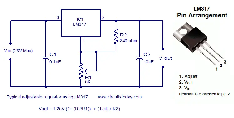
LM317-typical-adjustable-regulator-ckt.png
 

Put together a comparator circuit with LEDs as the output... You may use a piezo buzzer at the output. Ensure to use a limiting resistor for each. Hope this helps.:lol:
 

For low power, a power MOSFET and a decent heat sink with
a source sense resistor would do. You can put the V and I on
panel meters or datalog them; some data logging software
will let you build "gauges" to display stuff.
 

One way to demonstrate its regulation (or otherwise) would be to have a voltage monitoring op-amp driving a led, or even 3, with thresholds set to .1,1,10 mV. Then have a power transistor drawing the full current (BIG heatsink) and pulse it on/off at a low frequency , say 2 HZ. If its working correctly only the .1mV led should flash!
Frank
 

Something that lights up brightly is a fairly good bet. Because you will be asked, 'What is the maximum power your supply can put out?'

Maybe two automotive headlight bulbs in series? Or taillights? The bright LED type?
Or one bulb, as long as you're certain the current limiting function will bring the volt level down to 13V or so.
 

Status
Not open for further replies.

Part and Inventory Search

Welcome to EDABoard.com

Sponsor

Back
Top