neddie
Full Member level 5

- Joined
- Feb 23, 2010
- Messages
- 251
- Helped
- 41
- Reputation
- 82
- Reaction score
- 35
- Trophy points
- 1,308
- Location
- South Africa
- Activity points
- 3,026
Hi to all.
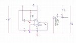
Anyone have experience with measuring a differential voltage in the supply line of a LM358. The datasheet shows it's input range going to the
+ and - supply rails , but it does not seem to work there. Simulation in Orcad and LTSpice shows the cct working , but in practice
no go. Is this a limitation of the 358 , that the model's don't reflect. Ive attached the basic cct.
Measuring a volt drop across a 1 ohm resistor in the supply line. If I move the lm358's supply above the original supply line by about 1Volt
then the circuit works fine. If it's the same or lower , then it stops working. Simulation does not show this behavior at all.
Cheers
Neddie