Continue to Site

Welcome to EDAboard.com

Welcome to our site! EDAboard.com is an international Electronics Discussion Forum focused on EDA software, circuits, schematics, books, theory, papers, asic, pld, 8051, DSP, Network, RF, Analog Design, PCB, Service Manuals... and a whole lot more! To participate you need to register. Registration is free. Click here to register now.

lm317 voltage problem

Status
Not open for further replies.

gauravkothari23

Advanced Member level 2
Joined
Mar 21, 2015
Messages
644
Helped
5
Reputation
10
Reaction score
4
Trophy points
1,298
Activity points
6,948
hi all....
i have a problem in getting output from lm317 ic. i am having a 12.5v input and expecting a ouput from range 3v to 8v. but the voltage does'nt drops below 11.50v. have also cheked the pin connection and also the datasheet. have also tried replacing the IC twice... but the problem contines. am also attaching my circuit diagram.

- - - Updated - - -

have also tried using 56 ohms resistance(R2). in this case the minimum voltage i get is 5v. but the voltage fluctuates a lot nearly 1v per sec. it does not stays stable.
 

Attachments

  • vo;tage.JPG
    vo;tage.JPG
    14.4 KB · Views: 125

check the voltage on the Vadjust pin. It should be 1.25V less than the output. There may be a problem with your variable resistor.
 

have tried changing my VR.... but still the problem continues......
is my cirucit correct... or i am missing any components.....
 

Are you sure of the value of R1?

Looks a tad high to me,try replacing it with a 1K pot and sticking a 560R on top.

Look at **broken link removed**

Also I'd increase the value of C1 to 100UF as well as haveing a 100n cap there.

See also **broken link removed**
 

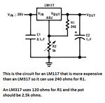
Your circuit uses 240 ohms for R2 which is used with the more expensive LM117 that is shown in every circuit in the datasheet. The LM317 should use 120 ohms then use half the value of the potentiometer, but the value of your pot is much too high anyway.
When the value of R2 is too high then the output voltage is too high when there is no load.

Your pot should adjust from zero ohms (a short) then the LM117 output should be 1.25V to 5k ohms when the output will try to be 27.3V.
Short the ADJ pin to ground which the pot should be able to do, then the output of the LM117 should be 1.25V.

With 120 ohms for R2 and you want 3V to 8V then the pot should be 168 ohms to 648 ohms.
 
The standard formula to calculate Vout for an LM317 using your assignment for R1 and R2 is:

\[V_{out}= V_{ref}(1 +\frac{R1}{R2}) + I_{adj}R1 \]

A typical value for R2 is 240Ω, as specified by most datasheets, however any reasonable value resistor in that range or less should work fine.

The adjustment pin current (Iadj) typically has a maximum value of 100µA, therefore the voltage drop across R1 is not particularly large.

The typical value for Vref is 1.25V, therefore the above formula can be simplified to:

\[V_{out} {\approx} V_{ref}(1 +\frac{R1}{R2}) \]

Notice Vout does not depend on Vin, although Vin must be large enough to account for the dropout voltage (VDO) which for the LM317 is typically a 2V maximum, instead relies largely on the device's Reference Voltage (Vref).

If the values of R2 and the desired Vout are known, then the following formula can yield approximate values for R1:


\[R1 {\approx} R2(\frac{V_{out}}{V_{ref}}-1) \]

For Vout = 8V and R2 = 240Ω, R1 ~ 1300Ω

For Vout = 3V and R2 = 240Ω, R1 ~ 340Ω


Of course if you lower the value of R2, then the required range of R1 can be encompassed by a 1kΩ pot.


BigDog
 

A typical value for R2 is 240Ω, as specified by most datasheets
The datasheets show 240 ohms with the more expensive LM117. The LM317 should use 120 ohms, R1 and R2 are the opposites in this thread.
 

Attachments

  • LM317 resistors.png
    LM317 resistors.png
    17.1 KB · Views: 97

... R1 and R2 are the opposites in this thread.

I've already accounted for the OP's designation of R1 and R2 when I posted the equations.

The datasheets show 240 ohms with the more expensive LM117. The LM317 should use 120 ohms...

I would be interested to know the manufacturer and date of the datasheet from which you obtained that image, it certainly isn't recent as I've not seen a combined LM117 and LM317 since the original National Semiconductor datasheet books decades ago. :grin:

While a 120Ω resistor maybe preferable in many cases, the use of a 240Ω resistor should still allow for the worst case minimum load current to maintain regulation (IO(min)) of 5mA in most cases.

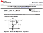
Oddly enough even the newer datasheets from TI, which appear to have been revised from new graphs, tables and text, still employ a 240Ω resistor in several of their example application schematics.

Latest TI LM317 datasheet:
TI-LM317.JPG

Latest ST LM317 datasheet:
ST-LM317.JPG


BigDog
 

I got my schematic of an LM117 from the same TI datasheet you show with an LM317 and the WRONG 240 ohm resistor like so many schematics show.
TI simply bought National Semi and made some mistakes when changing the National Semi logo to the new TI logo on the datasheets.
ST Micro also copied the error.
 

Attachments

  • LM317.png
    LM317.png
    39.8 KB · Views: 110

Regarding 120 versus 240 ohm, respectively 10 mA versus 5 mA minimal output current.

It's of course true that LM317 specifies 10 mA/120 ohm as worst case value, so it should be considered for a correct design.

But the point explains in no way the observations in this thread. If you acatually have a LM317 with worst case 10 mA minimal output current (it's really unlikely) and short the variable resistor, you won't get more than 2.4 V output, never 11.5 V. So there's obviously a much more basic problem with the circuit. Cheers.
 

How do you know how high the output voltage will rise when the resistor has the wrong value and the LM317 has high idle current? The datasheet says that when the resistor value is wrong then the output (voltage) will rise when there is no other load to pass the idle current.

I always design circuits using "worst case" parts values because when the typical current is 3.5mA and the max is 10mA then perhaps they had a yield with some of them close to 10mA. I like all of my circuits to work properly.
 

How do you know how high the output voltage will rise when the resistor has the wrong value and the LM317 has high idle current?

Simple question, simple answer. 10 mA*240 ohm = 2.4 V, with potentiometer adjusted for minimal (regular 1.2V) output. Generally, double the expected voltage for a specific setting.

To add another point, the datasheet figure 16 (in the recent TI datasheet), minmal output current versus input voltage suggests that even a LM317 with worst minimal output current won't exceed 5 mA with less than 15 V input. Because the worst case 10 mA specification is for full input voltage range. But strictly viewn, that's no specification.
 

The resistor value does not change the reference voltage of 1.25V between the output and the ADJ pin. The idle current of the entire circuit increases the output voltage if the resistor value is too high to load it.

Figure 16 shows a "typical" one that you cannot buy. You get a minimum one or maximum one or whatever they have.
So it is best to use 120 ohms with an LM317 then it will work perfectly even if the in-out voltage becomes near 40V.
 

Agree with every detail in your post. My only point was to question if the "120/240 ohm problem" can explain the observations in this thread.

Unfortunately it can't.
 

We do not know if the problem occurs only when there is no load and we do not know how high the output of an LM317 goes when the resistor value is too high and there is no other load.
 

Status
Not open for further replies.

Part and Inventory Search

Welcome to EDABoard.com

Sponsor

Back
Top