Continue to Site

Welcome to EDAboard.com

Welcome to our site! EDAboard.com is an international Electronics Discussion Forum focused on EDA software, circuits, schematics, books, theory, papers, asic, pld, 8051, DSP, Network, RF, Analog Design, PCB, Service Manuals... and a whole lot more! To participate you need to register. Registration is free. Click here to register now.

LM1084 overheating at just 250mA

Status
Not open for further replies.

jayanthyk192

Full Member level 3
Joined
Sep 17, 2010
Messages
179
Helped
1
Reputation
2
Reaction score
1
Trophy points
1,298
Activity points
2,580
Hi all,

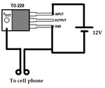
I needed a 5V-3A regulator. So, I bought myself an LM1084. I built the simple circuit(attached). I measured the output voltage and found it to be 5V. I connected this to my cell phone to test and the IC started heating up badly. I measured the current and found it to be around 250mA. I dont understand this. Please help me figure out the problem.

The IC is a fixed voltage(5V) LM1084. I even had a small heat sink on.

Thank you.
 

Attachments

  • 12v502.jpg
    12v502.jpg
    27.3 KB · Views: 142

Hi,

You may need to explain how, and why/testing what function?, you connected it to the phone. Heating up badly is appreciated description but a very relative concept, 250mA gives approx 1.75W. Have you done the calculations provided in the datasheet pages 10 and 11 of TI version? Was that open air, or in a small enclosure or something?

What sort of heat sink is it, C/W wise? I haven't used the LM1084, but with the 7805 and no heatsink or fans I avoid using it over 100mA (I like it's very stable voltage when used lightly), as it gets hot (warmer than I like touching once safely powered down), but not that smell of "nearly burning silicon and metal hot".

Sorry to ask a stupid question: the connection to the phone wasn't accidentally reverse polarity was it? Easy to do with those barrel connector adapters.
 

I do not see the capacitors on your circuit described in the datasheet for the LM1084 so maybe the regulator was oscillating at a very high frequency that will make it get hot.
 

Hi,

You may need to explain how, and why/testing what function?, you connected it to the phone. Heating up badly is appreciated description but a very relative concept, 250mA gives approx 1.75W. Have you done the calculations provided in the datasheet pages 10 and 11 of TI version? Was that open air, or in a small enclosure or something?

What sort of heat sink is it, C/W wise? I haven't used the LM1084, but with the 7805 and no heatsink or fans I avoid using it over 100mA (I like it's very stable voltage when used lightly), as it gets hot (warmer than I like touching once safely powered down), but not that smell of "nearly burning silicon and metal hot".

Sorry to ask a stupid question: the connection to the phone wasn't accidentally reverse polarity was it? Easy to do with those barrel connector adapters.

I wanted to just check if the 5V was proper. I measured it and just connected it to my phone. The voltage was still 5V. Current at 250mA. The heat sink was in air. It was hot enough for me not able to hold the sink for more than 2 seconds. I'm not sure about the temperature. But at 250mA, I dont think it should heat up that much. Even without the sink, it should be just warm. So, any ideas?

I do not see the capacitors on your circuit described in the datasheet for the LM1084 so maybe the regulator was oscillating at a very high frequency that will make it get hot.

I added the capacitors later (10uF) without any success.

- - - Updated - - -

@d123, The polarity was proper and the phone was also charging.
 

Hi,

Thanks, for the update, you've saved me waffling on needlessly there... :)

Are you trying to use it as a mobile phone (battery) charger? If so, you'd need a battery charger IC for that specific phone battery I imagine.

...Hmmm, I may be wrong about needing a battery charger IC, apparently that circuitry is inside phones.

I do think having the heat-sinking calculations clear is important for what is around 1.75W dissipation by the regulator to rule out that - for example, something like a 23ºC/W heat-sink that may be too high a C/W value.
 
Last edited:

Hi,

Thanks, for the update, you've saved me waffling on needlessly there... :)

Are you trying to use it as a mobile phone (battery) charger? If so, you'd need a battery charger IC for that specific to the phone battery I imagine.

Not as a charger. I need it to run my Raspberry Pi. I wanted to just try it on my cellphone. I don know why:-D. But then the overheating's happening.
 

...if you think of hot water, a 50ºC shower would not be a nice experience, or holding something at that temperature, or beach sand burning feet in summer..., add 10 or 20ºC and that's very hot indeed, so it's possible the regulator is running hot but if it's working fine, then no problem. If it overheats to the point of shutting down, that is a different matter.

When you use it with your Pi, I guess you'll do the heat-sinking properly and maybe use a small fan which will help dissipate heat and help it run cooler.

I had once tried an LM7805 with my phone and it worked without heating, even without a heat sink. I though this would have lower voltage drop and consequently lower heat and temperature, atleast for small current. I now tried with a new IC, but the same happens. I even added a 100uF cap, without any success.
 

The datasheet says to use an output capacitor that works properly at high frequencies like 10uF tantalum. An input capacitor also might be needed. The capacitors must have short leads and be very close to the pins on the LM1984 so do not use a solderless breadboard.
Its heating should be exactly the same as a 7805 since they are both linear and both have the same voltage across them and the same current through them, (12V - 5V) x 250mA= 1.75W.

Instead of using a 12V power supply, try 9V. Then the heating is (9V - 5V) x 250mA= 1.0W.
 

"LM1984" - slip of the typing finger or deliberately accidental, Audioguru? Like saying the uA19741
 

The datasheet says to use an output capacitor that works properly at high frequencies like 10uF tantalum. An input capacitor also might be needed. The capacitors must have short leads and be very close to the pins on the LM1984 so do not use a solderless breadboard.
Its heating should be exactly the same as a 7805 since they are both linear and both have the same voltage across them and the same current through them, (12V - 5V) x 250mA= 1.75W.

Instead of using a 12V power supply, try 9V. Then the heating is (9V - 5V) x 250mA= 1.0W.

I am using a 10uF electrolytic one. I just tried the same circuit with a 7805 and the same happened. Overheating! I googled "7805 cell phone charger" and found a bunch of circuits. All of them use a 2ohm resistor. Is this the blunder I was making?

Did you calculate the overall thermal resistance Rjc+Rca and measure the temperature rise of case? and follow advice on caps close to regulator leads?

Did you read this ?
https://www.ti.com/general/docs/lit/getliterature.tsp?baseLiteratureNumber=spra953&fileType=pdf

Thank you for the document. I didn't calculate any thermal quantities before. I'll do in the future.
 

A series 2 ohm resistor with 250mA in it has a voltage drop of 0.5V then the phone gets only 4.5V instead of 5V. One wrong circuit in Google uses 15 ohms then if there is 250mA in it the voltage drop is 3.75V and the phone gets only 1.25V! I think the charger circuit in the phone limits the current so the phone and charger do not catch on fire. The charger circuit in the phone needs 5V.
 

unheatsunk to220 dissipating 1.75w is going to get very scalding hot...what you see is just normal, by all means put a dropping power resistor coming off the 12v to take some of the dissipation out of the to220.
 

The stupid circuits in Google show a series resistor between the output of the 5V regulator and the cell phone like this one:
 

Attachments

  • bad cell phone charger circuit.png
    bad cell phone charger circuit.png
    34.5 KB · Views: 159

unheatsunk to220 dissipating 1.75w is going to get very scalding hot...what you see is just normal, by all means put a dropping power resistor coming off the 12v to take some of the dissipation out of the to220.

I dont think my case is "unsinking" I have a sink and the room temperature will be around 22. ANd what 220 are you referring to?

The stupid circuits in Google show a series resistor between the output of the 5V regulator and the cell phone like this one:

Yeah, that is awful. That image appears in top of the search.

Anyway, I'll just connect this to my Raspberry Pi (possible only on Monday) and see what happens. Meanwhile are there any ICs that don't burn off like this one?
 

I mean "TO220"....Common regulator package.
So you have a little heatsink?.......still 1.75w in a to220 with small heetsink is going to get a bit toasting still.....you said you could keep your fingers on it for 2 seconds so it cant have been that hot anyway
 

I mean "TO220"....Common regulator package.
So you have a little heatsink?.......still 1.75w in a to220 with small heetsink is going to get a bit toasting still.....you said you could keep your fingers on it for 2 seconds so it cant have been that hot anyway

Initially It'll be cool. But then after a minute or so it gets extremely hot. I'm sorry I dont have a high temperature sensor and talking in terms of "really hot" is bad.
 

yes, but seriously, fingers are very good, they don't need calibrating .....as long as you don't electrocute yourself, fingers are great.
 

Status
Not open for further replies.

Similar threads

Part and Inventory Search

Welcome to EDABoard.com

Sponsor

Back
Top