Continue to Site

Welcome to EDAboard.com

Welcome to our site! EDAboard.com is an international Electronics Discussion Forum focused on EDA software, circuits, schematics, books, theory, papers, asic, pld, 8051, DSP, Network, RF, Analog Design, PCB, Service Manuals... and a whole lot more! To participate you need to register. Registration is free. Click here to register now.

lm 386 new sample for earphone amp.

Status
Not open for further replies.

rajaram04

Advanced Member level 3
Joined
Jun 17, 2012
Messages
871
Helped
6
Reputation
12
Reaction score
5
Trophy points
1,298
Location
earth
Visit site
Activity points
7,687
LM386 sample practice.jpg


HELLO ALL

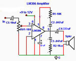
Here above i ve posted a schematic for an earphone amp.& i connected it after a simple china made sheap USB player.From the designs i obtained from net i preaped it & it has ability to boost bass a lil.bit , its working all the way like that

so now what to do for raise of treble part , please help :) thanks
 

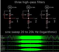
C5 and RV1 create a high pass filter. The values shown will cut the bass frequencies slightly.

Changing C5 makes a cheap and easy way to shift the response curve.

By adding a resistor across C5, it allows you to shape the curve further.

Examples below. The 100 ohm resistor is RV1.

 
C5 and RV1 create a high pass filter. The values shown will cut the bass frequencies slightly.

Changing C5 makes a cheap and easy way to shift the response curve.

By adding a resistor across C5, it allows you to shape the curve further.

Examples below. The 100 ohm resistor is RV1.


sir actually RV1 is 100k i am using or a large amout of signal is entering the unit causing a loud sound & heavy noise at the speaker so please get me design as per that at the input . . thanks
 

sir actually RV1 is 100k i am using or a large amout of signal is entering the unit causing a loud sound & heavy noise at the speaker so please get me design as per that at the input . . thanks
The 100k input volume control should have a logarithmic taper which is also called "audio taper". An audio taper pot is usually marked "A" and a linear pot is marked "B".
When a linear pot is turned down to half then the signal is cut in half which still sounds very loud. But when an audio taper pot is turned down to half then the signal is reduced to 1/10th and sounds reduced.

Of course the poor little low power LM386 makes heavy noise when its output is clipping because with a 9V supply its maximum output with low distortion is only 0.45W into 8 ohms and this drops as the 9V battery voltage runs down.
Since the bass frequencies are boosted then the maximum output power with low distortion for all other frequencies is reduced to about 0.11W which is almost nothing.

EDIT: The title says "earphone amp" but the text says "speaker". An earphone plays extremely loud with 0.45W but most earphones are not 8 ohms, they are 32 ohms today so their maximum bass power from this amp will be about 0.2W when the supply is 9V.
 
Last edited:
The 100k input volume control should have a logarithmic taper which is also called "audio taper". An audio taper pot is usually marked "A" and a linear pot is marked "B".
When a linear pot is turned down to half then the signal is cut in half which still sounds very loud. But when an audio taper pot is turned down to half then the signal is reduced to 1/10th and sounds reduced.

Of course the poor little low power LM386 makes heavy noise when its output is clipping because with a 9V supply its maximum output with low distortion is only 0.45W into 8 ohms and this drops as the 9V battery voltage runs down.
Since the bass frequencies are boosted then the maximum output power with low distortion for all other frequencies is reduced to about 0.11W which is almost nothing.

EDIT: The title says "earphone amp" but the text says "speaker". An earphone plays extremely loud with 0.45W but most earphones are not 8 ohms, they are 32 ohms today so their maximum bass power from this amp will be about 0.2W when the supply is 9V.


actually the diagram i found on net . . .
I edited it as per my configuration i am applying for present . .
i forgot to vary the word speaker but its exactly a nokia 2690 original earphone i am connecting
each side shows near about 60 ohms

Now so how to overcome the problem of gain distortion etc etc etc ?

Should i try a diffrent IC ?/

what about 4558 ??

Or you say how to proceed ?
 

You need to attenuate the signal further. (It's similar to the problem of tapping TV speaker leads, to record the audio into a tape recorder. The level is so strong it overwhelms the input and creates distortion.)

Add another resistor in series before the volume control. 100K may be enough.

Also you can try adding a resistor to ground before the volume control. (Not too different from how the volume control itself works.)

I cannot be certain but there is a chance your USB player is designed to see some amount of load at the output. It may need this even though it is solid state.
A 100 ohm resistor to ground could be sufficient for this purpose.


exactly where to connect the 100 ohm resistor ?
I connected to the input & ground but its making a complete black out of sound on output
 

Do you have a logarithmic (audio taper) volume control or is it a linear pot?
The volume control is supposed to adjust the input level of the signal. If it is too loud and is causing distortion then simply turn it down without adding another resistor.

The LM386 power amp will oscillate and cause distortion if it is missing a supply bypass capacitor (it is not shown on your schematic) and if it is built on a solderless breadboard. When powered from a 9V battery it can produce a very loud and clear output to one 60 ohm earphone or two in parallel. The LM386 is cheap so its hiss might be heard.
A 4558 is an old dual opamp that has a minimum allowed supply of 10V and like most opamps it has trouble driving a load that is less than 1k ohms or 2k ohms.


i hv both audio taper & linear one
but on bread board i applied taper one & result was not so good but when i lowered the level of USB player then i got the output without distortion & ya i connected the input without a resistor in series , its ok & going well

& where to apply a bypass capacitor ???

& whichj IC is good for the purpose fo earphone ?
 

The supply bypass capacitor (10uF to 470uf) connects from the positive supply pin 6 of the LM386 to its power ground pin 4.
**broken link removed** has many excellent circuits but they use opamps that are probably not available in your country.
 
The supply bypass capacitor (10uF to 470uf) connects from the positive supply pin 6 of the LM386 to its power ground pin 4.
**broken link removed** has many excellent circuits but they use opamps that are probably not available in your country.


Yeah yeah i connected a 1000 uf cap. from pin 6 to pin 2 & 4 which i hadn't shown there

Its not a problem of things available in my country actually
its a problem of finding in my area

suppose if get things from outside in a price 4 times of original then there is no use of making it as i ve my aim of building things with convenience to general people
 

I was going to tell you to look for Headphones Amplifier Circuit in Google Images but many circuits are awful.
An OPA2134 dual opamp from Texas Instruments is an excellent stereo audio opamp and can provide a maximum output of 37.5mW RMS per channel into a 60 ohms headphone.
But many people want to damage their hearing with 100mW RMS.


sir i asked a local dealer for OPA2134 & he is showing me some 22134

are they same or totally a diffrent one ?
 

sir i asked a local dealer for OPA2134 & he is showing me some 22134

are they same or totally a diffrent one ?
22134 is not a complete part number. An OPA2134 is made by the Burr-Brown division of Texas Instruments.
 

Attachments

  • OPA2134 details.PNG
    OPA2134 details.PNG
    17.2 KB · Views: 130
22134 is not a complete part number. An OPA2134 is made by the Burr-Brown division of Texas Instruments.


yeah i got its datasheet & too found some of its equivalent functional IC numbers

LM4562
LME49720

please check
 

Status
Not open for further replies.

Part and Inventory Search

Welcome to EDABoard.com

Sponsor

Back
Top