cupoftea
Advanced Member level 5
If synch rects are used with LLC, then a suitable delay must be used in the drive to the synch rect FETs. This is the case whether you are operating above or below the “upper resonant frequency”.
The attached 2 LTspice simulations (the ones with "2 diode" output, not FWB) show the perils of not using the delay (just remove the delay blocks to see it without the delays).
So, somehow, your LLC control needs to be able to spot how far above or below the “upper resonant frequency” you are in order to implement the requisite delay………AYK, the delay must be as short as possible, so as to maximise efficiency, but not so short that the situation described is violated……but the further from “upper resonant frequency” you are, the longer the delay needs to be.
The ICE2HS01G LLC controller purports to be able to always correctly assess and implement the delay. However, would you agree, its doubtful that under all conditions of load/line transients, startup, re-start, brownout, return from brownout, etc etc etc……it couldn’t possibly always properly assess and implement the delay?……its related to the reverse recovery problem in LLC’s…..and how its impossible for any controller to be able to guarantee always avoiding harsh reverse recovery……unless of course it’s the LLC controller demo’d by Infineon which purports to be able to detect reverse recovery by software before it actually happens…and then simply avoid switching the FETs during such intervals….but even that software’s true success is not truly known?.....(if it did what it said…then it would truly be a Nobel prize candidate.)
So would you agree that synch rects in LLC converters are dodgy?……….unless you have a very tame application which never has the situations such as transients etc, as listed above…..or unless you have the magic Infineon type software.
...I mean, the overvoltages etc that happen when synch rects go wrong can seriously weaken, and reduce the lifetime of, the LLC, even if they dont blow it up at the time....maybe it blows up after the warrantee period so you're OK...who knows.
This post tells you what most of the App Notes dont about reverse recovery in LLC's.....(which is the related situation to the problem with synch rects discussed here)
ICE2HS01G LLC controller
___---___----___--____----___---___---____--____--____
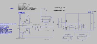
As can be seen, the attached (LTspice and jpeg) is a 2kW HB LLC with a Full Wave Bridge output. You can save power by making the bottom two output diodes synchronous……….and with a fixed 750ns (or more) delay between 2ndary synch rects and primary FET……you are fine no matter what fault conditions are encountered. (because the other diode in the FWB protects you). This is the only robust way to do synchronous FETs with an LLC converter (ie, with FWB and only make 2 of the 4 synchronous)…..other ways are OK only if you have highly complex control software and sensing in order to mitigate the ruinous electrical conditions that can come with synch rects and LLC.
I pity many who have got LLC designs which ignore the above...their field failure rate could end up being very large......as is known, many PSU's rarely get turned ON to above 10% power in their life, so they are ok...but others...well...
So do you agree, the attached "2 out of 4" synch rects with the FWB output is the only good way for LLC with synch rects?
The attached 2 LTspice simulations (the ones with "2 diode" output, not FWB) show the perils of not using the delay (just remove the delay blocks to see it without the delays).
So, somehow, your LLC control needs to be able to spot how far above or below the “upper resonant frequency” you are in order to implement the requisite delay………AYK, the delay must be as short as possible, so as to maximise efficiency, but not so short that the situation described is violated……but the further from “upper resonant frequency” you are, the longer the delay needs to be.
The ICE2HS01G LLC controller purports to be able to always correctly assess and implement the delay. However, would you agree, its doubtful that under all conditions of load/line transients, startup, re-start, brownout, return from brownout, etc etc etc……it couldn’t possibly always properly assess and implement the delay?……its related to the reverse recovery problem in LLC’s…..and how its impossible for any controller to be able to guarantee always avoiding harsh reverse recovery……unless of course it’s the LLC controller demo’d by Infineon which purports to be able to detect reverse recovery by software before it actually happens…and then simply avoid switching the FETs during such intervals….but even that software’s true success is not truly known?.....(if it did what it said…then it would truly be a Nobel prize candidate.)
So would you agree that synch rects in LLC converters are dodgy?……….unless you have a very tame application which never has the situations such as transients etc, as listed above…..or unless you have the magic Infineon type software.
...I mean, the overvoltages etc that happen when synch rects go wrong can seriously weaken, and reduce the lifetime of, the LLC, even if they dont blow it up at the time....maybe it blows up after the warrantee period so you're OK...who knows.
This post tells you what most of the App Notes dont about reverse recovery in LLC's.....(which is the related situation to the problem with synch rects discussed here)
Avoiding reverse recovery problems in LLC converters - Page 1
Avoiding reverse recovery problems in LLC converters - Page 1
www.eevblog.com
ICE2HS01G LLC controller
___---___----___--____----___---___---____--____--____
As can be seen, the attached (LTspice and jpeg) is a 2kW HB LLC with a Full Wave Bridge output. You can save power by making the bottom two output diodes synchronous……….and with a fixed 750ns (or more) delay between 2ndary synch rects and primary FET……you are fine no matter what fault conditions are encountered. (because the other diode in the FWB protects you). This is the only robust way to do synchronous FETs with an LLC converter (ie, with FWB and only make 2 of the 4 synchronous)…..other ways are OK only if you have highly complex control software and sensing in order to mitigate the ruinous electrical conditions that can come with synch rects and LLC.
I pity many who have got LLC designs which ignore the above...their field failure rate could end up being very large......as is known, many PSU's rarely get turned ON to above 10% power in their life, so they are ok...but others...well...
So do you agree, the attached "2 out of 4" synch rects with the FWB output is the only good way for LLC with synch rects?