Continue to Site

Welcome to EDAboard.com

Welcome to our site! EDAboard.com is an international Electronics Discussion Forum focused on EDA software, circuits, schematics, books, theory, papers, asic, pld, 8051, DSP, Network, RF, Analog Design, PCB, Service Manuals... and a whole lot more! To participate you need to register. Registration is free. Click here to register now.

Linear Tracking Power supplies Thoughts Help!

Status
Not open for further replies.

Deltatango

Member level 1
Member level 1
Joined
Jan 28, 2006
Messages
34
Helped
0
Reputation
0
Reaction score
1
Trophy points
1,288
Activity points
1,621
I am working on an old Booton signal generator with a linear supply it has a tracking system for its +/- 15v rail, this seems to have suffered some problems of stability I would guess.
On the LM301 ic with an earlier circuit a capacitor with a value under 1nF was used between pins 1 and 8.
Then in a later circuit this becomes 10nF and a 100uF tantalum added to its negative rail control device.

Now this machine I am working on has those capacitors at 100nF betwen pins 1 and 8, but to confuse me more those two other 100nF used on the regulator ic's input have been modified to now connect to a different position to its diagram.

I understand that linear regulators need small capacitors to be stable, but I am confused to the best option when used in this configuration I just need advice on the best course of action to tidy up a messy worked on power supply.

Many thanks from David Modified Boonton power supply.jpg
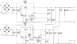
 

probably a transcription error, only a few 10's of pF are needed, usually
 

On the LM301 ic with an earlier circuit a capacitor with a value under 1nF was used between pins 1 and 8.
Then in a later circuit this becomes 10nF and a 100uF tantalum added to its negative rail control device.

Now this machine I am working on has those capacitors at 100nF betwen pins 1 and 8, but to confuse me more those two other 100nF used on the regulator ic's input have been modified to now connect to a different position to its diagram.
Looks like they are designing feed back loop by trial and error method. Agree with Easy peasy that 10nF or even 100 nF is far beyond usual LM301 compensation capacitor range, but it may be intentionally nevertheless.

Cascading default compensated LM301 with UA7805 gain would surely result in unstable loop. You either need local feedback for the LM301 stage or create a dominant loop gain pole by other means. I doubt that the presented solution gives particularly good dynamic behavior.
I am working on an old Booton signal generator with a linear supply it has a tracking system for its +/- 15v rail, this seems to have suffered some problems of stability I would guess.
On the LM301 ic with an earlier circuit a capacitor with a value under 1nF was used between pins 1 and 8.
Then in a later circuit this becomes 10nF and a 100uF tantalum added to its negative rail control device.

Now this machine I am working on has those capacitors at 100nF betwen pins 1 and 8, but to confuse me more those two other 100nF used on the regulator ic's input have been modified to now connect to a different position to its diagram.

I understand that linear regulators need small capacitors to be stable, but I am confused to the best option when used in this configuration I just need advice on the best course of action to tidy up a messy worked on power supply.

Many thanks from DavidView attachment 171218
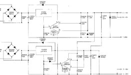
I had a manual for the early version of my Booton 102 which is shown in diagram 1.
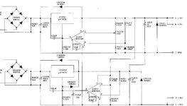
With the actual Booton I have got it came with a photocopy of a manual with modifications shown in diagram 2
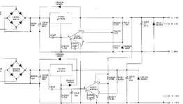
On my Booton I have found that it differs again as in diagram 3, though the parts used are in period so are original to it.

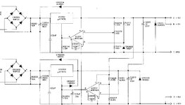
In the final diagram 4 its previous owner had made a further change (as noted with bridged links) just wish to understand which might be better option, or is there a further adaption which could be made.

In general with the circuit based around RF output there is "very little" high value capacitors used in its modules, only some in the modulation section.1-Early Boonton power supply.jpg2-Later Boonton power supply.jpg3-My Actual Boonton power supply.jpg4-My Modified Boonton power supply.jpg
 

I have looked at other linear tracking supplies which mostly use opposite voltage regulators with an IC, while mine uses two 7805 types to create +/- 15v but not seen that many circuits with this set up, is that the reason I wonder for it being unstable a design.

If the circuit in diagram 1 is used as a base design with 30pf comp, could anyone suggest any other mods to try rather than damping it down with large capacitors etc as in diagram 4.

Think that using 78xx in this way may not be so good as they were designed for a grounded "adj" pin.

Thanks for any help from David
 

mine uses two 7805 types

My simulation is a simplified pattern of your setup. The common ground is a point where the two supplies are connected to become quasi-bipolar. Yet no short-circuit occurs.

Each load receives 5V. Ampere draw need not be identical.

This topology is able to work because your two diode bridges appear to be independent of each other. If this schematic serves as an indicator then it should be okay for you to use two positive regulator IC's.

2 quasi-bipolar connected 5v suppies using 2 NPN 2 zeners 2 9V sources.png
 

Status
Not open for further replies.

Similar threads

Part and Inventory Search

Welcome to EDABoard.com

Sponsor

Back
Top